Problem
I want a knob that I can twiddle in my FPGA design to adjust a constant. But I don’t want to wire up some kind of digital potentiometer or encoder or anysuch garbage
Solution: capacitor + resistor + inout
The circuit:
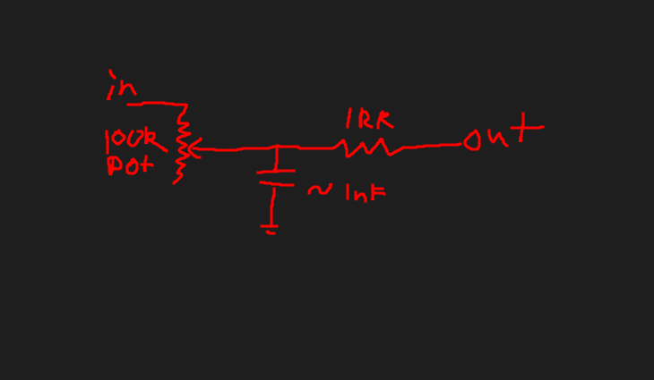 We’ll get the FPGA to charge a capacitor through a variable resistor and measure how long that takes. Then we discharge the capacitor quickly through the measuring port and repeat the process.
Verilog
The code is this simple:
module usr_knob (
    input clk,
    inout gpio_drv,
    inout gpio_meas,
    output reg [63:0] period_out,
);
    parameter MEASURING = 1'b0;
    parameter DISCHARGING = 1'b1;
    reg [1:0] state;
    reg [63:0] period_meas;

    assign gpio_meas = (state == MEASURING) ? 1'bz      : 1'b0;
    wire in_meas = (state == MEASURING)     ? gpio_meas : 1'b0;
    assign gpio_drv = (state == MEASURING)  ? 1'b1      : 1'bz;
    wire in_drv = (state == MEASURING)      ? 1'b1      : gpio_drv;

    always @(posedge clk) begin
        case(state)
            MEASURING: begin
                if (in_meas) begin
                    period_meas <= 0;
                    period_out <= period_meas;
                    state <= DISCHARGING;
                end else begin
                    period_meas <= period_meas + 1;
                end
            end
            DISCHARGING: begin
                // Once the capacitor has been discharged we reset the state:
                if (!in_drv) begin
                    state <= MEASURING;
                end
            end
        endcase
    end
endmodule
The results look like this:
Analog
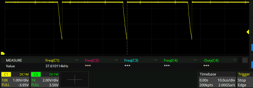
The driving pin looks like this:
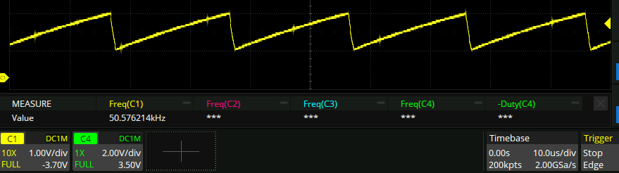
 and the capacitor node looks like this:
 Works with a frequency range of 16kHz-1.5MHz. Nice! The 16kHz frequency has a jitter of about 600ns. Seems pretty good to me and might be comparable with the oscillator jitter itself, if I bothered to measure.
Analog meets digital
Interestingly when I connect this circuit to other stuff in the fpga to actually do something useful, the jitter increases enormously:
 like 10us of jitter!
All I did was hook it up to a counter like so:
like 10us of jitter!
All I did was hook it up to a counter like so:
    reg [63:0] usr_knob_period;
    usr_knob usr_knob_instance(
        .clk(clk48),
        .gpio_drv(usr_knob_drv),
        .gpio_meas(usr_knob_meas),
        .period_out(usr_knob_period),
        .state_(rgb_led0_b)
    );
    assign led_strobe = rgb_led0_b;

    reg [63:0] wave_generated;
    wire wave_reference = wave_generated >= usr_knob_period;
    counter_64bit rate_generator(
        .clk(clk48),
        .out_value(wave_generated),
        .reset(wave_reference)
    );
    assign pulse_out = wave_reference;
the interaction between the two modules is through the usr_knob_period variable. So I thought that if I could mutate the variable in between the two modules, then they wouldn’t be hooked up directly any more and wouldn’t interact directly. Adding 1 to the usr_knob_period doesn’t help, but multiplying it does! not enough to solve the problem, but a fair bit.
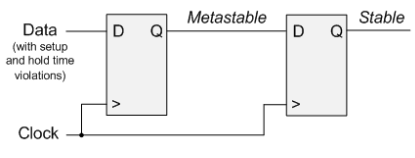
Metastability??
Apparently this is a thing, and it affects fpgas and me in particular. When sampling an incoming signal that is not synchronous with the clock you must sync it up first. handy diagram:
 The adjusted code:
...
    assign gpio_meas = (state == MEASURING) ? 1'bz      : 1'b0;
    wire in_meas_raw = (state == MEASURING)     ? gpio_meas : 1'b0;
    assign gpio_drv = (state == MEASURING)  ? 1'b1      : 1'bz;
    wire in_drv_raw = (state == MEASURING)      ? 1'b1      : gpio_drv;

    reg in_meas_metastable;
    reg in_drv_metastable;
    reg in_meas;
    reg in_drv;
    always @(posedge clk) begin
        in_meas_metastable <= in_meas_raw;
        in_drv_metastable <= in_drv_raw;
        in_meas <= in_meas_metastable;
        in_drv <= in_drv_metastable;
...cont
This should just delay things by a couple clock cycles but not affect the program otherwise.
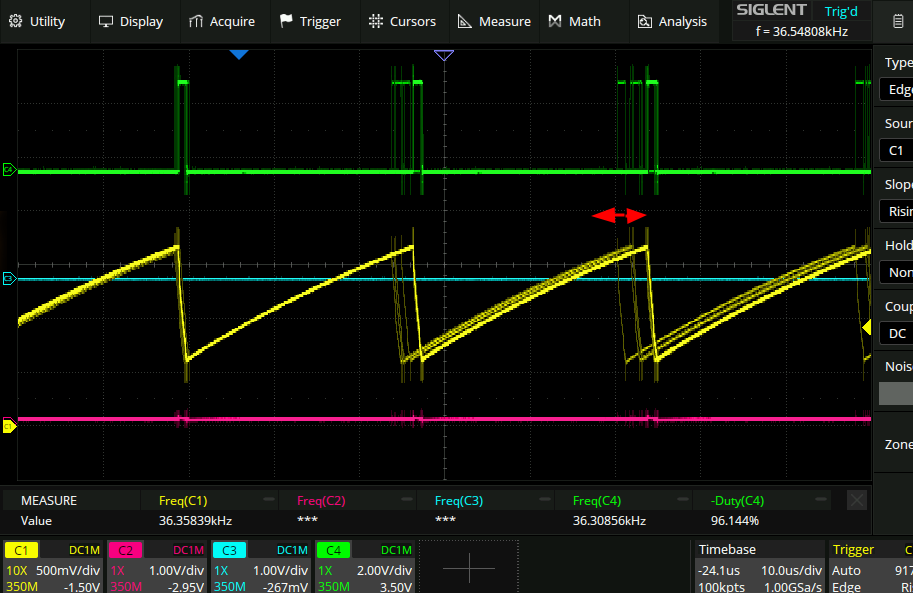
Here is a histogram of when the edges occur for the default user knob with nothing attached to it (blue), the knob with an output attached (orange, and the aforementioned high jitter), and a knob with an output attached and also input latching (green):
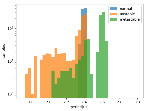 Looks like adding in the metastability stuff didn’t have much effect other than slowing down the period. I am surprised that it was slowed down by that much, but there you go.
TL;DR
Just like ESD and reinterpret_casts, you don’t need to worry about metastability.