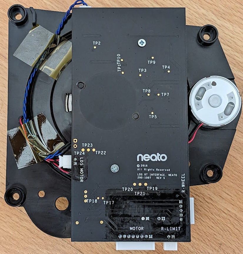
Outside

Inside
This is actually upside down with respect to the ground I think:
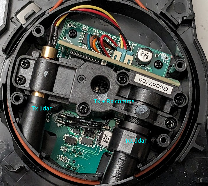
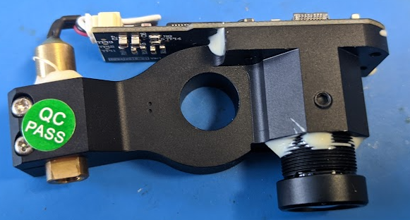
The Tx is in an oddly long enclosure. Overall this bears a striking resemblance to an RP-lidar that I’ve seen previously:
Baseboard side:
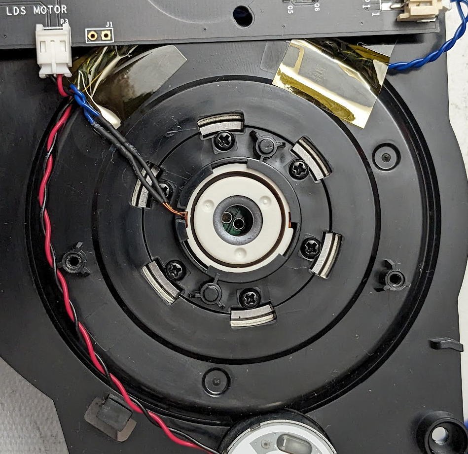
You can see here a tx led and an rx photodiode. The opposite side has the same thing, so presumably they operate at a bit different wavelength with a bandpass filter on the photodiode. You can buy photodiodes with bandpass filters for pretty cheap for stuff like TV remotes.
Communications
I was going to leave the teardown at that but there’s actually an extremely convenient and labelled 0.1” header strip located on the spinning board:
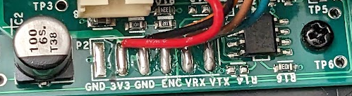 I soldered to this and powered it on and it drew around 20mA of current. Spinning the lidar by hand you can see that there are around a dozen encoder pulses per revolution. I suspected that there was a laser safety interlock style thing preventing it from operating any further, so I provided a fake encoder signal via the waveform generator on my scope and the lidar immediately began to draw 200mA, which was very encouraging.
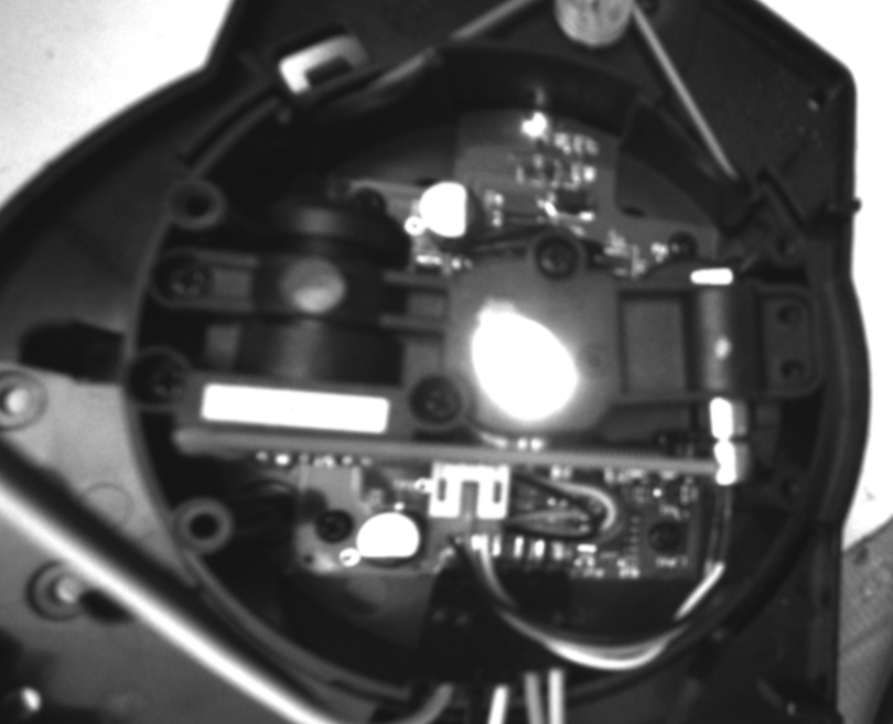
Sadly still no light coming out of the Tx, though. I can connect to the tx with a bench supply from the connector of course and verified that it was outputting in the infrared using a realsense camera (which has no IR filter on it).
I soldered to this and powered it on and it drew around 20mA of current. Spinning the lidar by hand you can see that there are around a dozen encoder pulses per revolution. I suspected that there was a laser safety interlock style thing preventing it from operating any further, so I provided a fake encoder signal via the waveform generator on my scope and the lidar immediately began to draw 200mA, which was very encouraging.
Sadly still no light coming out of the Tx, though. I can connect to the tx with a bench supply from the connector of course and verified that it was outputting in the infrared using a realsense camera (which has no IR filter on it).
Tx (Photons)
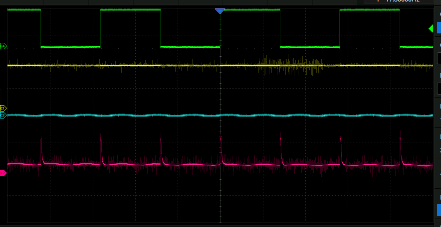
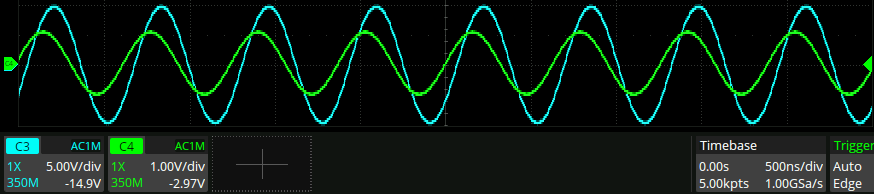
Here is he “VTX” labelled waveform on oscilloscope:
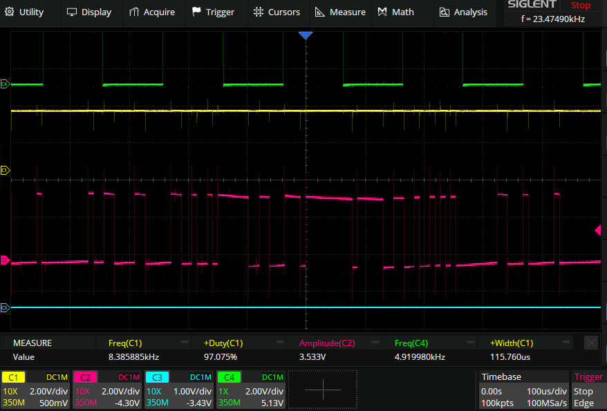
Green: fake encoder Pink: Tx signal Shining light on the rx with the emitter of a realsense didn’t get anything to happen. Here is the firing behaviour of the laser: once on each encoder edge:
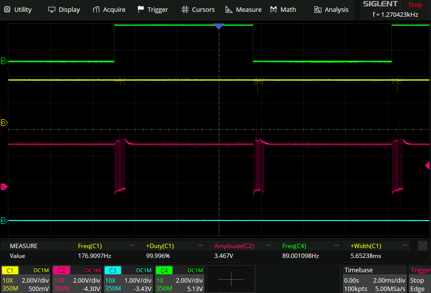
Nice and simple! This only seems to happen for a limited range of encoder frequencies, and there’s also some hysteresis where if you power cycle the unit while applying an encoder signal it might go from no lock→a lock. I was hoping that when the tx firing synced itself to the encoder edges that would indicate that the firmware was happy and begin firing, but this appears not to be the case. It probably requires an extremely specific encoder frequency to get things to work and I can’t be bothered with all that.
Tx (comms)
Ir picture of data being sent out:
Extremely terrible trace from a photodiode measuringthe tx light:
Given that it’s taking a measurement once per encoder edge it seems pretty clear that it’s just sending out the distance it receives each time. Maybe the distance is encoded as a pulse width, maybe it’s some kind of serial thing.
It’s a serial thing
Taking the thing apart a little further exposes the tx led. The waveform looks like this:
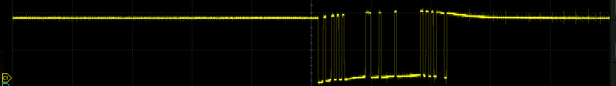
It’s changing all the time, but it’s not clear if it’s a distance measurement.
Anyway, I still can’t get the laser to fire. I’m sure that there’s some encoder speed based laser safety thing going on here where if the motor is spinning at the exact right speed the laser will fire and won’t otherwise.
Rx (photons)
Interestingly the lens has at least two elements to it: .
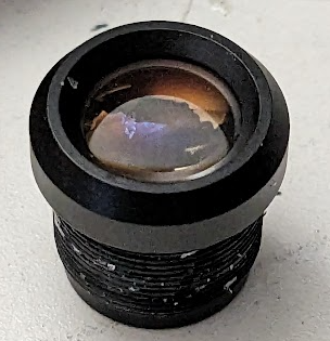
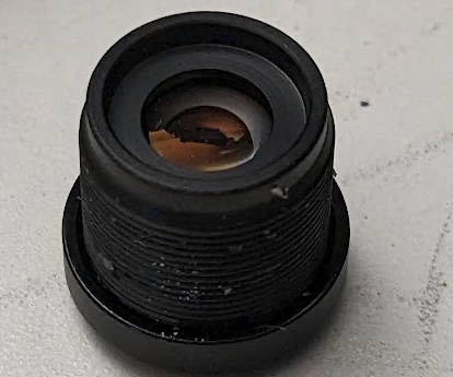
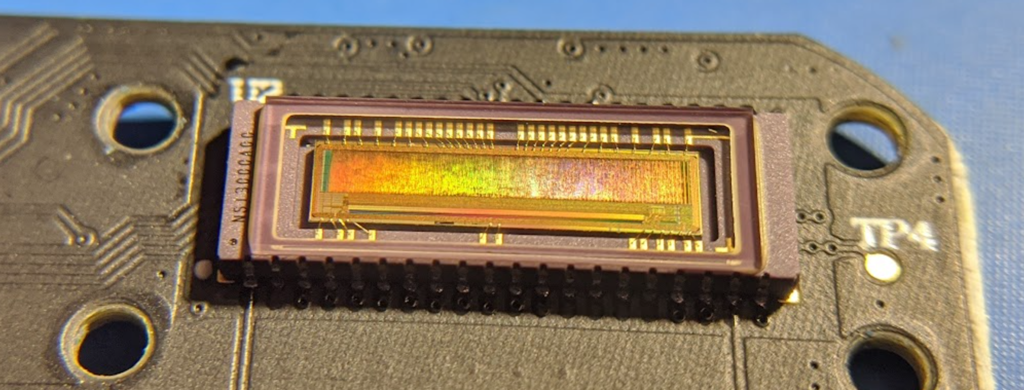
Which is a lidar CMOS sensor. Given the angle between the Tx and the Rx (notice they are bent together slightly in above pics) the position of the spot on the sensor indicates how far away something is:
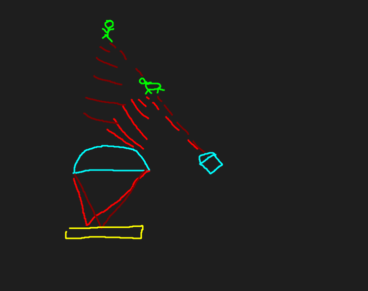
Since a lens is an object that transforms the incoming angle of light to a location at the focal plane.
Power transfer
here is the RF coil that transfers power across the gap:
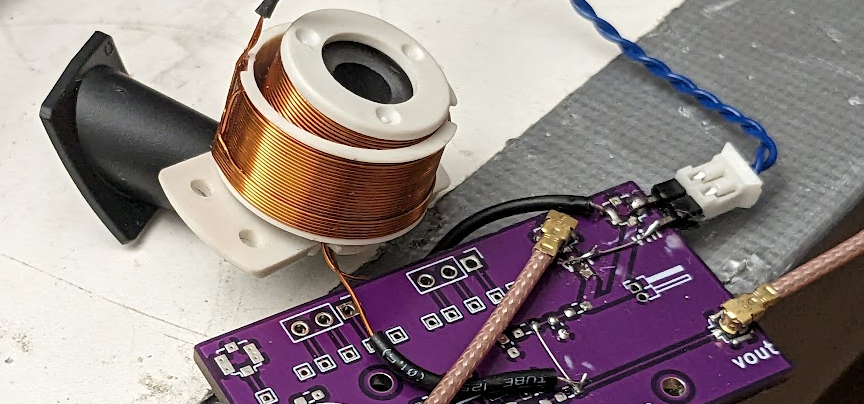
I have attached it here to some coax like so:
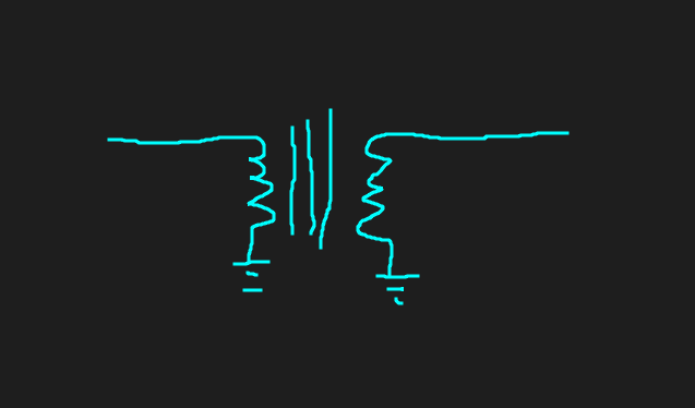
So as to be able to measure the Bode plot using my oscilloscope:
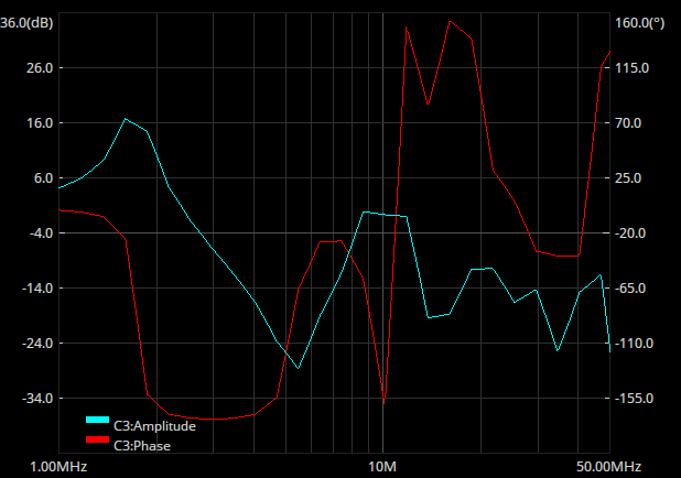
23dB of gain. Something something turns ratio.
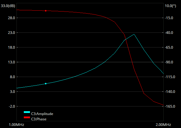
This is indeed a “real” measurement, when I take the coils out from each other the peak disappears. Sanity check measurement where I put in a single frequency at 1.6MHz:
Noice. Interestingly, when I take the ferrite core out nothing much seems to change. Maybe that only has an effect under load or something?