Pinout
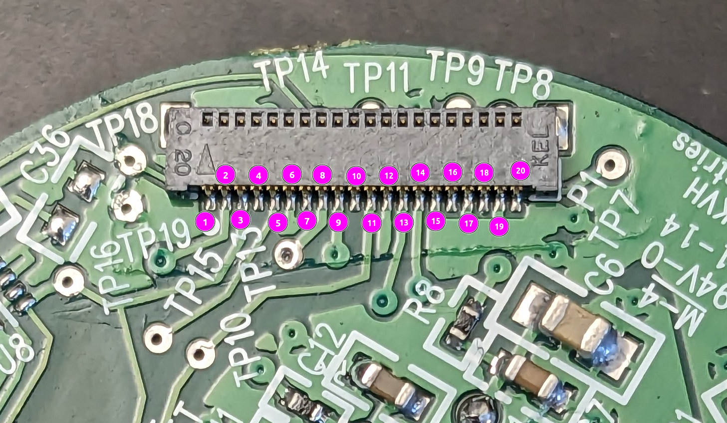 20 pin connector. Total width from the start of the first pin to the start of the next is 9.49mm. So a pitch of 0.4745mm. Call it 0.5mm I suppose.
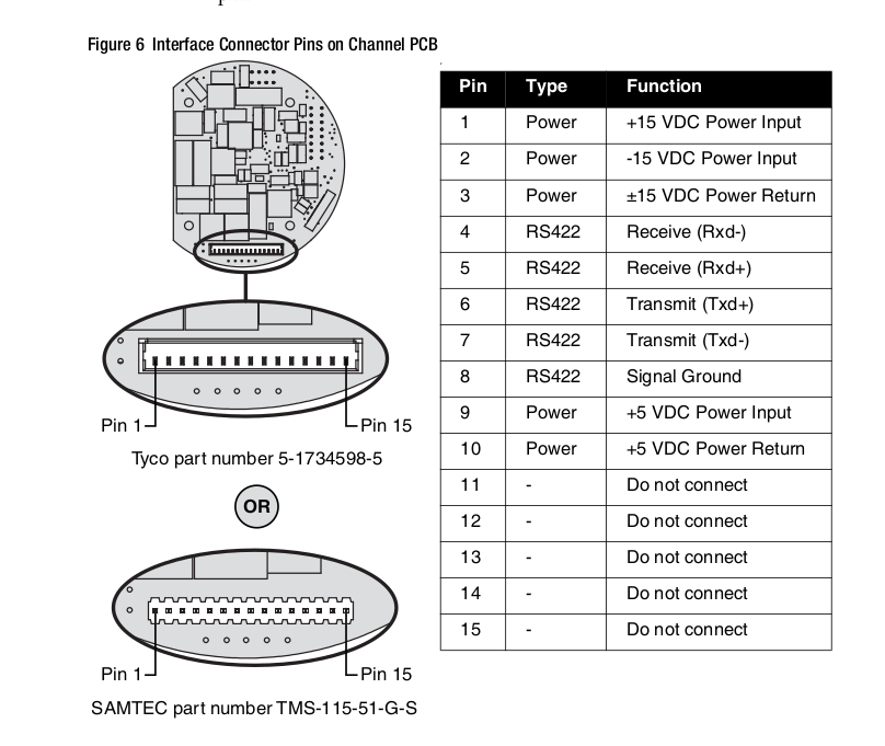
This is the interface for the communication board, which is not the flex cable above:
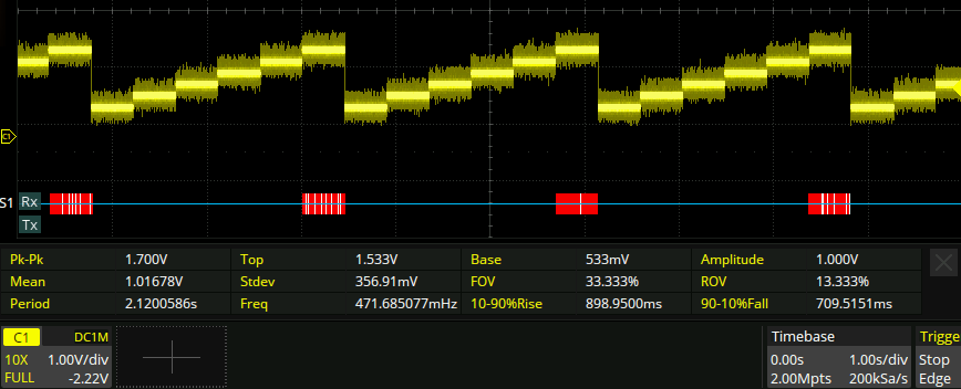
Powering it up and connecting a suitably padded flex cable between the actual gyro and the controller+psu PCB, the ‘valid’ bit of the serial output is 0 and the measured rate is also exactly 0.
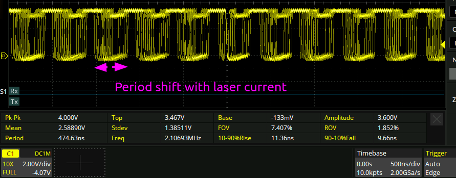
The measured laser current however seems to be changing a few times per second from around 23 to 53mA. That seems wack. But, lo! I also found this test point on the fiber gyro board:
Note the time axis here. here is a plot of the measured laser current as a function of time:
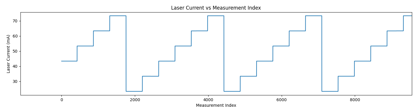
A Clue!
This is the test point in question:
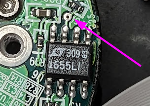
Which is the Vout pin of the LTC1655, a 16 bit rail to rail DAC. So perhaps then the gyro is going through an initialization routine and can’t get out of it?
Interestingly, some of the test points sweep through 6 values and others through 5.
Literature
I found the book “Design and development of fiber optic gyroscopes”. It has a design segment just on the DSP-1750, and has this block diagram in it:
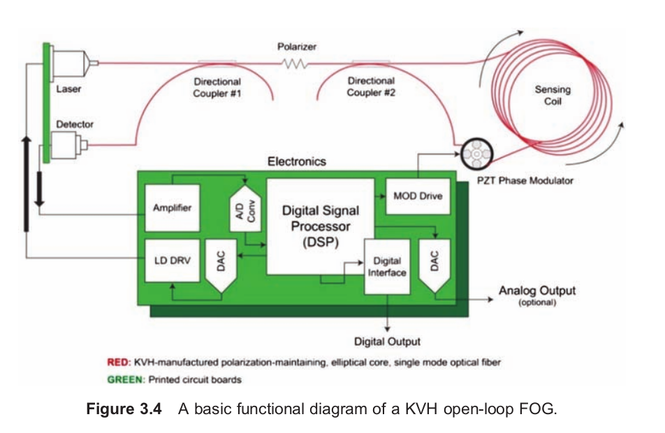
This has three connections to the fiber system. There are two through hole connectors that I can see on the fiber board, a 5 pin one in a ring, and a weird 2 pin one that seems to have no voltage on it at all (this is in agreement with the below observations on the DAC input being flat, though).
I had naively assumed that the output of the gyro was like an FMWC lidar; there would be some beat frequency that would be measured. But it seems that’s not the case:
The scientific principle behind the FOG is the Sagnac effect, which is also
the basis of the ring laser gyro. When the fiber coil is not rotating, the optical path length in both directions is the same, so the two counter-rotating optical
signals are in phase upon their return to the detector. Rotating the coil
introduces an optical phase difference in the counter-rotating light paths
known as the Sagnac phase shift. The phase difference in the two paths results
in a change in amplitude of the recombined signals proportional to the
rotation rate. As such, the FOG is often referred to as an interferometer.

The piezoelectric (PZT) modulator is driven with a sinusoidal signal to
bias the Sagnac interferometer at the most-sensitive operating point. The
open-loop gyroscope has a first-order sinusoidal response to rotation, and the
SF is dependent on the optical intensity and modulation depth. The
interferometer converts this modulation into an output signal comprising
harmonics correlating to the Bessel functions. All of the required information
to determine the rotation rate and stabilize the SF is extracted from the
fundamental signal up to its fourth harmonic
Possible output:
The last pin of the flex cable has this signal on it:
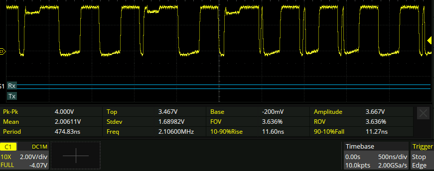
A single snapshot of which looks like this:
Another interesting signal on the flex cable:
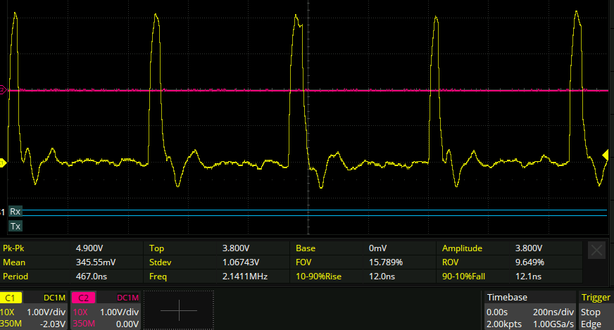
Actually both of the above signals originate from this chip:
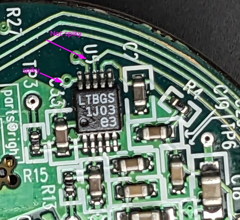
This is a LTC1403AIMSE 14 bit ADC:
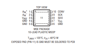
It would appear that I was looking at the CONV/SCK/SDO lines. The CONV line is the spiky one above. This means that when the duty cycle was changing above, that was the magnitude of the digital signal changing, not the frequency of an analog one. Kind of weird because when I probe pins 1 and 2 of the chip with the probe AC coupled and zoomed in to 5mv/div, I see basically no change whatsoever on the input. The chip also does not have an internal amplifier, so it’s not just that it’s too low for the scope to measure.
So the next step is to take a reading of the digital signals, which will require probing the CLK+SDO lines concurrently. Probably the CONV line would help, too.
Decoding
The clk/serial/data lines look like this after some gentle massaging coming out of the scope:
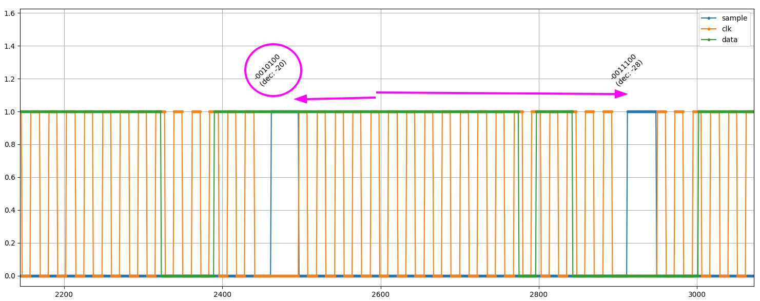
Decoding a whole bunch more data than that leads to this trace of some samples:
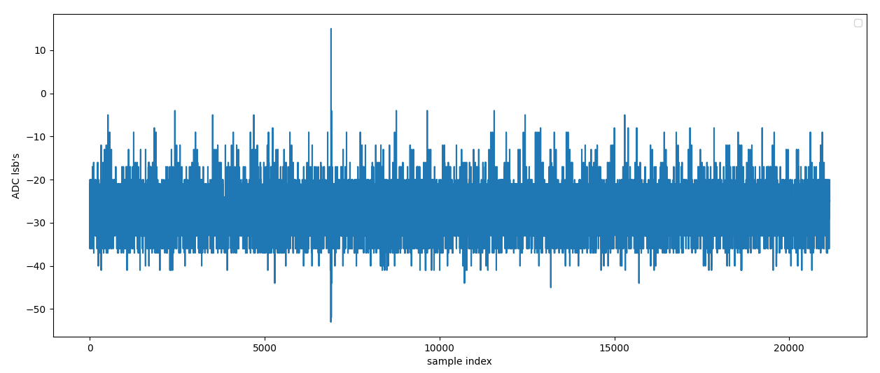
…Noise. note that the above trace is only for a few milliseconds of data, and the laser current changed every few hundred milliseconds. But there’s no signal much larger than this showing up at any time, that was verified before by just probing the input to the ADC with the scope.
So at this point the most likely problem is the laser not being driven properly, or the photodiode being broken. Given that they are most likely fiber coupled devices, if either the laser or the photodiode proper are broken then it’s game over.
Schematic reverse engineering

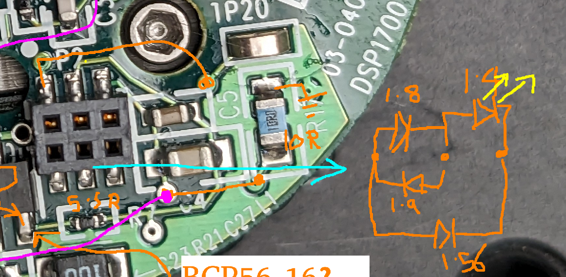
Light:
The three pin connector that goes to the laser package has a bewildering array of diode drops measurable, even when only the package is being measured (it’s not connected to the rest of the circuit). Presumably the three pin package is a laser diode + monitor photodiode package. But there are no less than 4 different diodes measurable between the three terminals, so it’s not clear which is which
I have a realsense camera, which does not have an IR filter. So it can see ~900nm light no problem. Often these things are 1550, but it’s worth a shot to try and put a small amount of current through all the diodes and see if something emits.
With no voltage applied:
With the diode tester of my multimeter between two of the laser package terminals:
There is light!
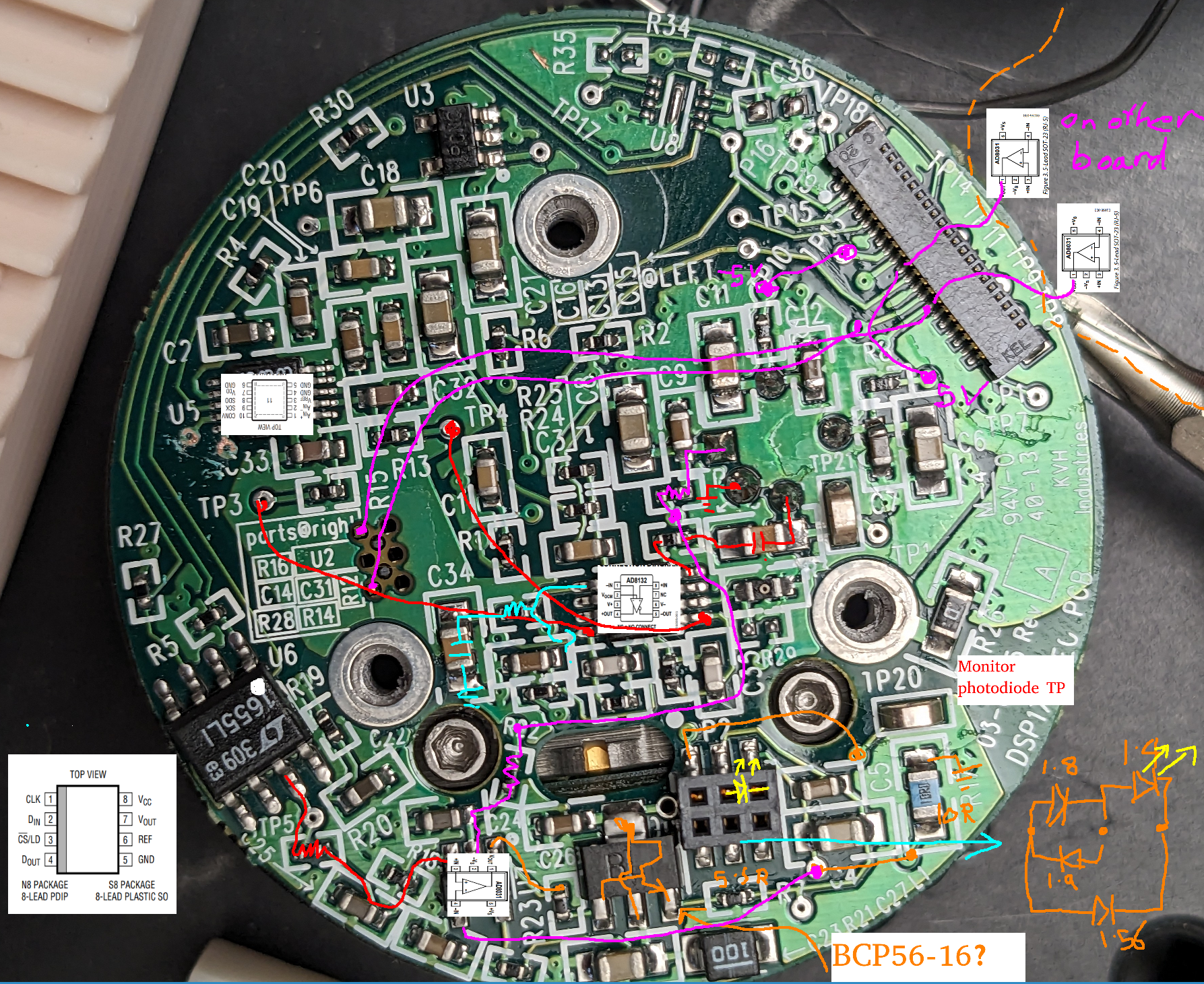
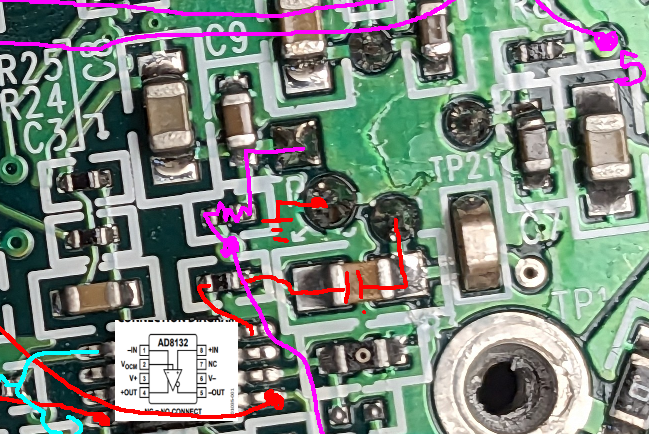
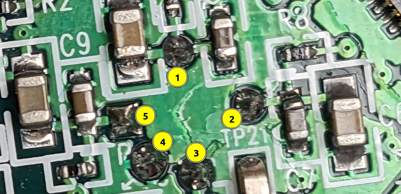
here is the pcb annotated with the diode drops:
Aside: photodiode pics
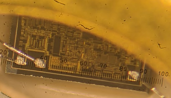
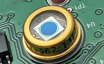 The photodiode on the flip side of the board is interesting. It has a whole microchip inside for some reason:
This is perhaps the reason that it needs +/-5V supplies: an integrated amplifier of some kind.
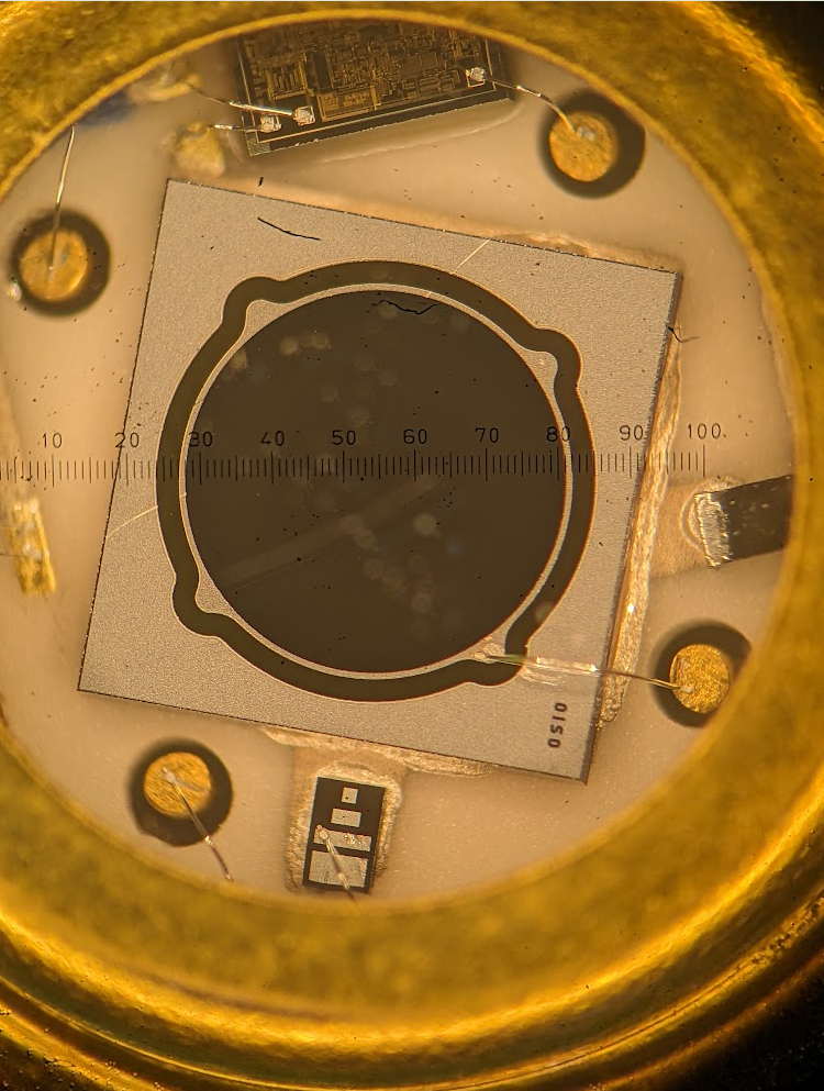
As far as I can make out, the text on the bottom of the chip at the ‘50’ mark reads:
ADI
1997  BJ6 MG
825 SO JBP
How does this even work?
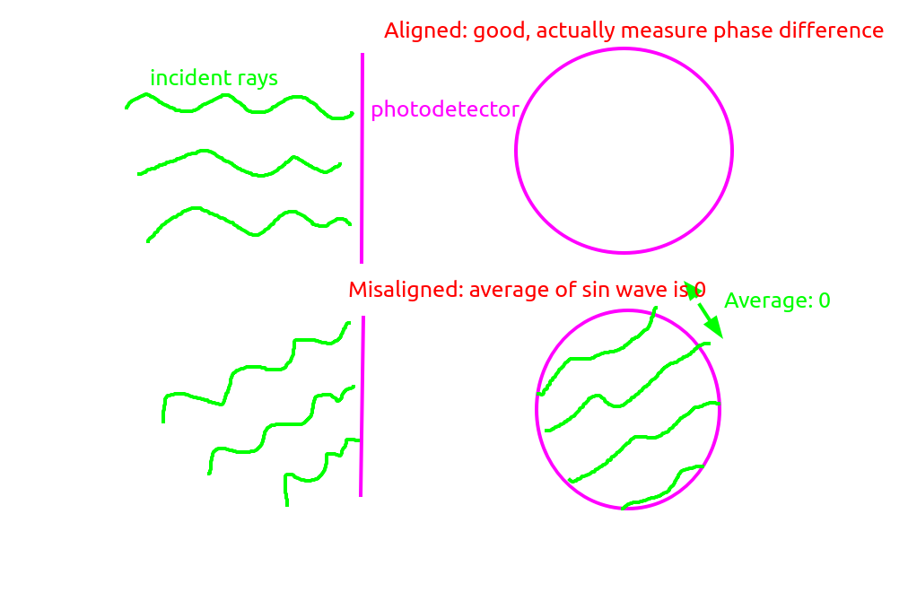
A fiber optic gyro is an interferometric device. In an interferometer, the whole surface of the photodiode must be normal to the rays being interfered with, otherwise fringes will form and the photodiode will measure the average of the signal across many sin wave periods, which is 0.
However this is a huge photodiode, with a diameter of like 2.5mm. That means that the tolerance for tilting of the photodiode is
ChatGPT
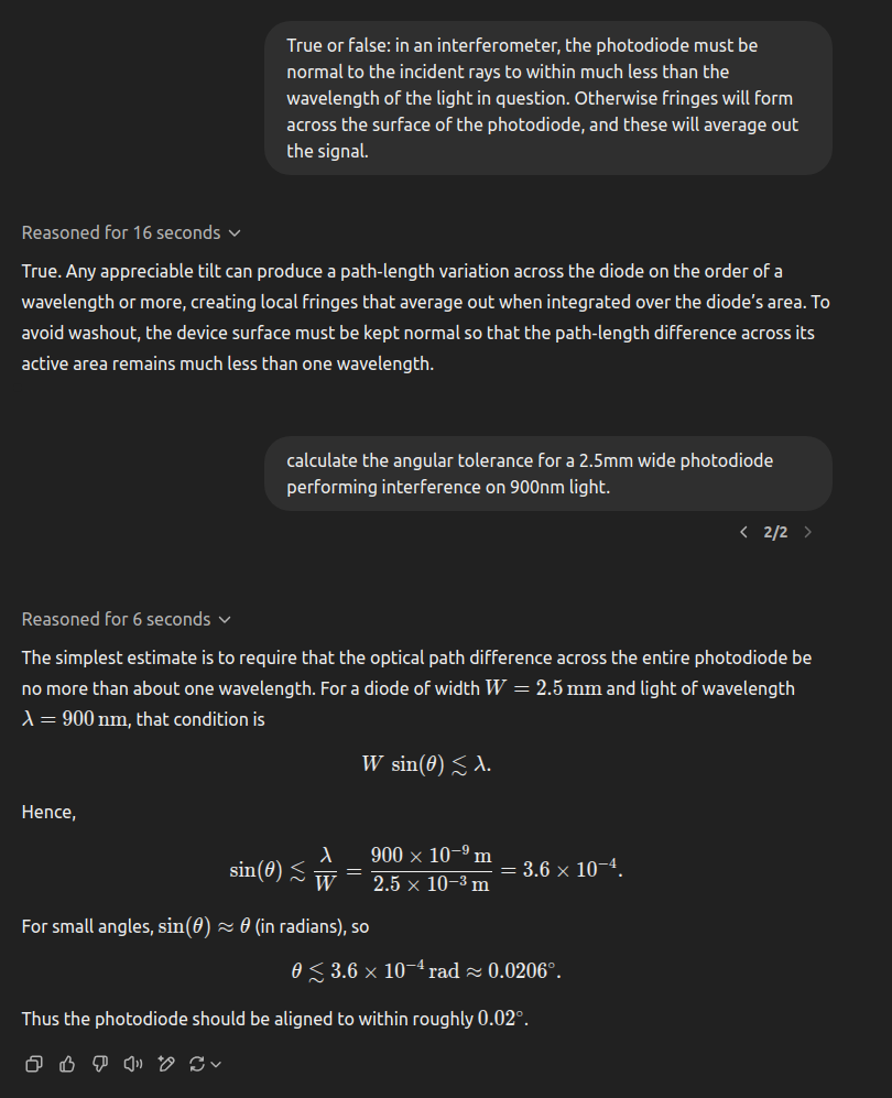
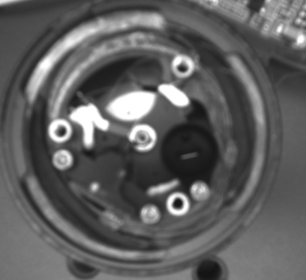
~0.02 degrees. This photodiode is mounted on a PCB which is randomly sitting on top of the case like so:
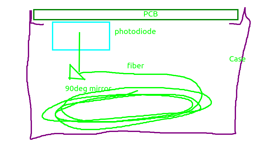 There is no way that the photodiode can have a tolerance like that to the mirror. Of course the beam can be much smaller than that, but even if it’s 0.2mm then that’s still 0.2deg, which also doesn’t seem likely
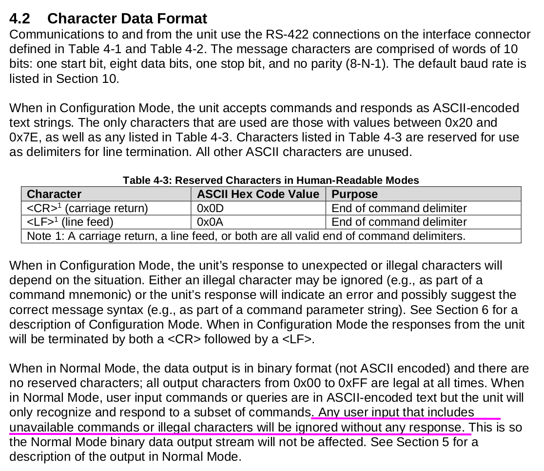
Talking to it
The DSP-750 has no documentation that suggests you can send it commands. However, the DSP-1760 (a full imu, not just a fiber gyro) includes this command table:

So I opened up the arduino serial port and sent a bunch of them. Here is me sending the =config command:
Looks like it’s just being ignored. The manual says this:
Second unit, second life
One of the things that most disturbs me about the gyros is that the voltage output of the photodiode is basically zero always. I saw light earlier coming out of the laser and the photodiode has an internal amplfier in it, so it’s definitely possible for it to be busted.
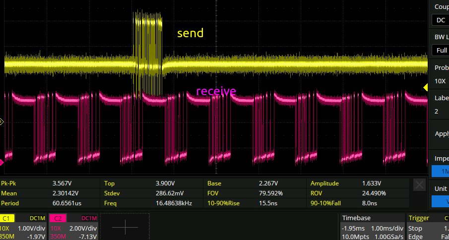
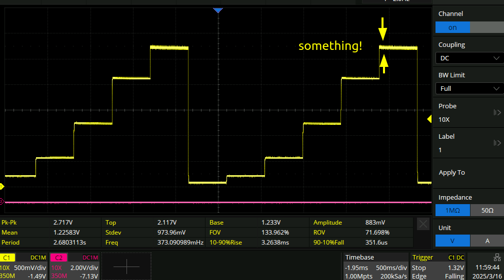
For lack of anything else to do I plugged in the second unit to see if there was anything different. And there is! here is the output from the second one:
Zoomed out in time, showing the different laser currents:
Zoomed in and AC coupled to the highest current:
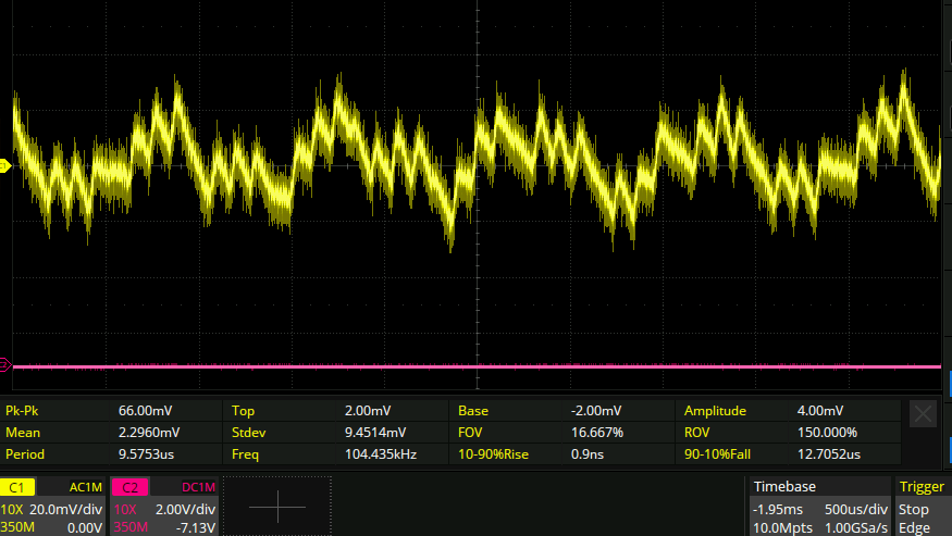
Recall that the PCB itself actually has an AC coupled output to the photodiode:
So this is all tying together and fits in to what I thought before: The controller board is stepping through a bunch of laser currents until it finds a receive signal. However it never finishes its initialization. The fact that it found a signal on the last possible value of laser current suggests that something is out of wack and it can’t step far enough.
From the above section on the angular tolerance of the photodiode I stuck a calibrated spacer made of a 32awg wire insulation into the gap between the PCB and the gyro case. And now it works! I can integrate it over time no problem. It seems to be mostly measuring the earths rotation rate as expected. It’s also incredibly sensitive as expected, jumping up and down on my concrete slab floor gives a loud and clear signal. Pushing sideways on the desk gives an oscillation that takes a few seconds to die away.
The second gyro
The second gyro was not amenable to the same treatment as the first, the output of the amplifier seems stuck at -3.8V and doesn’t change with the laser current. Now to do a comparison of the voltages. This should be a lot easier now there is one that’s working.
1: -4.6V 2: 4.6V 3: 0V 4: 0V 5: -4.6V
So it looks like it’s just measuring 0V. It occurs to me that when I measured the laser light above I did so on the unit I was not using at the time, which was the one that turned out to work. Let’s do the same measurement on this one, for which no light is being measured. I checked the TIA die inside the photodiode by the way, and didn’t notice anything frazzled.
Two different hardware revisions:
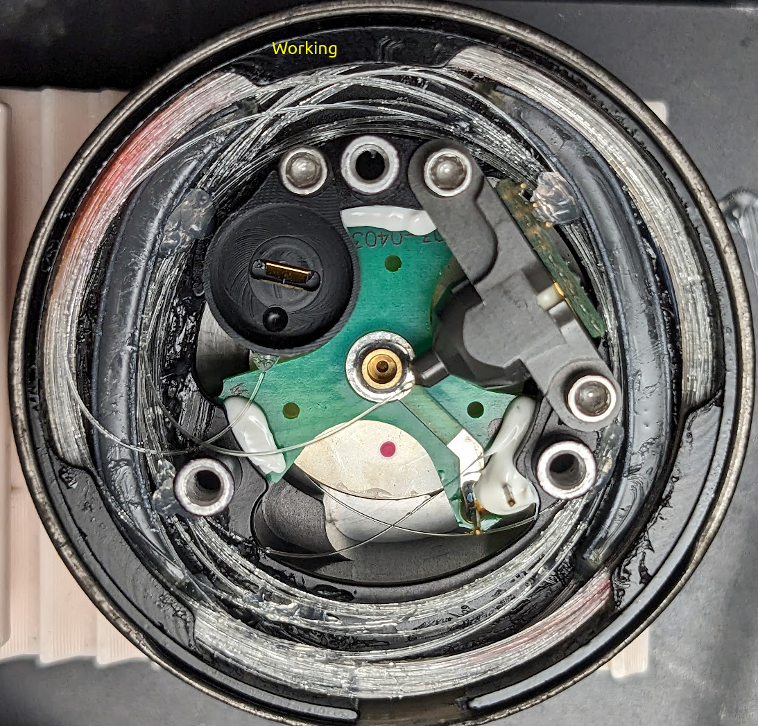
This is what the one that works looks like:
And this is what the one that doesn’t looks like:
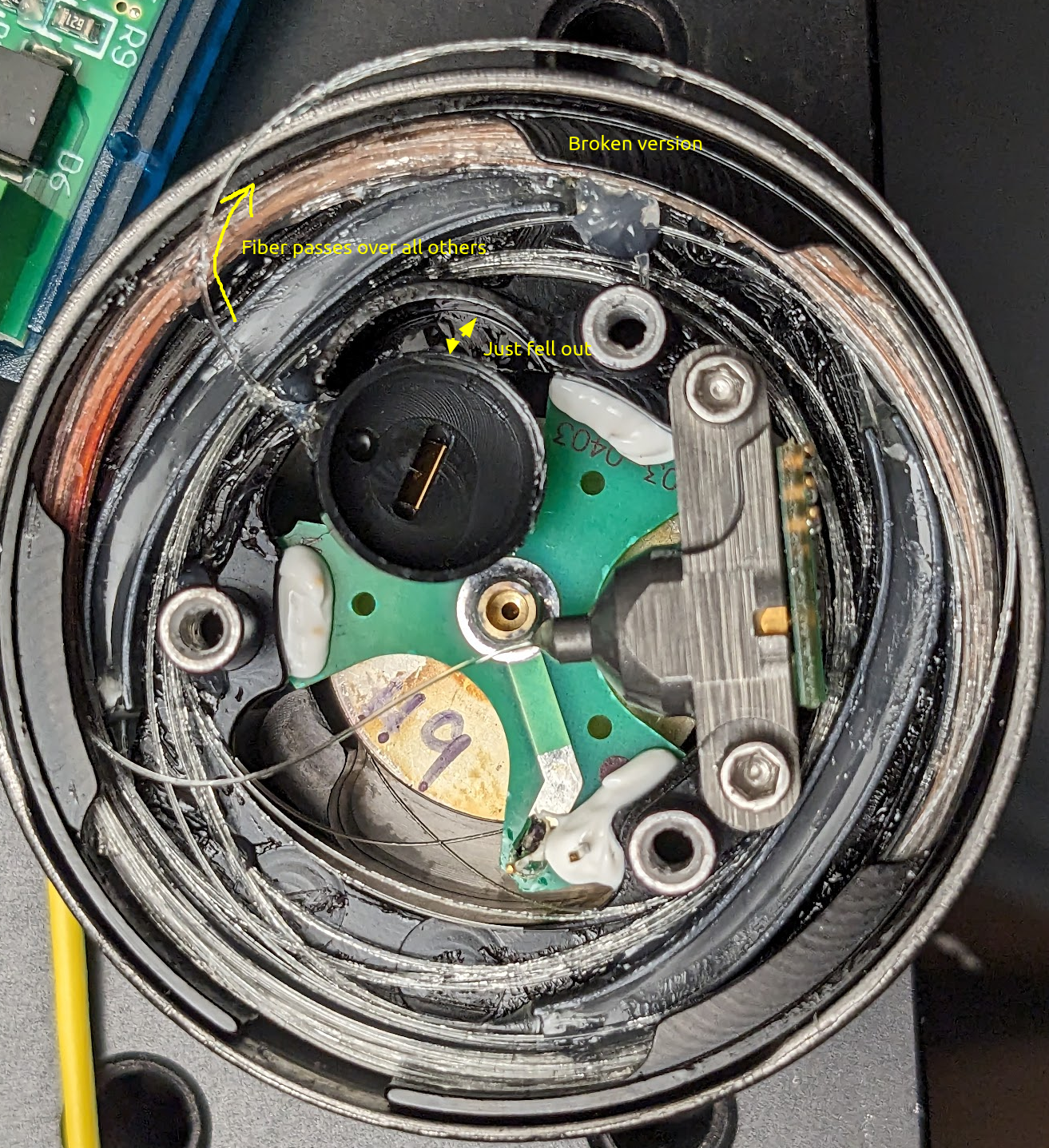
The broken ones mirror isn’t bolted down and is flapping in the breeze! And there isn’t even a way to bolt it down either! This makes no sense at all. In addition to being a different hardware revision this one has also been assembled differently, the fiber for this one passes over the others and has a tendency to pop out of the casing. The previous one had the fiber coming out of the mirror pass under some others and was much better controlled. For posterity, the ‘A’ gyro is the one that works.
Light output
The gyro that works has light clearly coming out of the mirror. The one that doesn’t, doesn’t. I can see that there is light coming out of the laser as it leaks out the bottom of the package. however there is absolutely zilch coming out of all other areas. I think this is the root cause of the issue this particular gyro has. Light is clearly coming out of the laser, and not coming out of the fiber that’s supposed to go to the photodiode. Not much I can do about that.
Still though, the fact that the location of the mirror is so incredibly poorly constrained, and the small shifting of the PCB from the previous gyro fixing it entirely means that I’m not 100% satisfied.