The goal here is to precisely control the temperature of a water bath, for recrystallizing copper sulfate crystals. I have a esp32, a hotplate stirrer and a temp sensor off amazon.
Hotplate stirrer mod
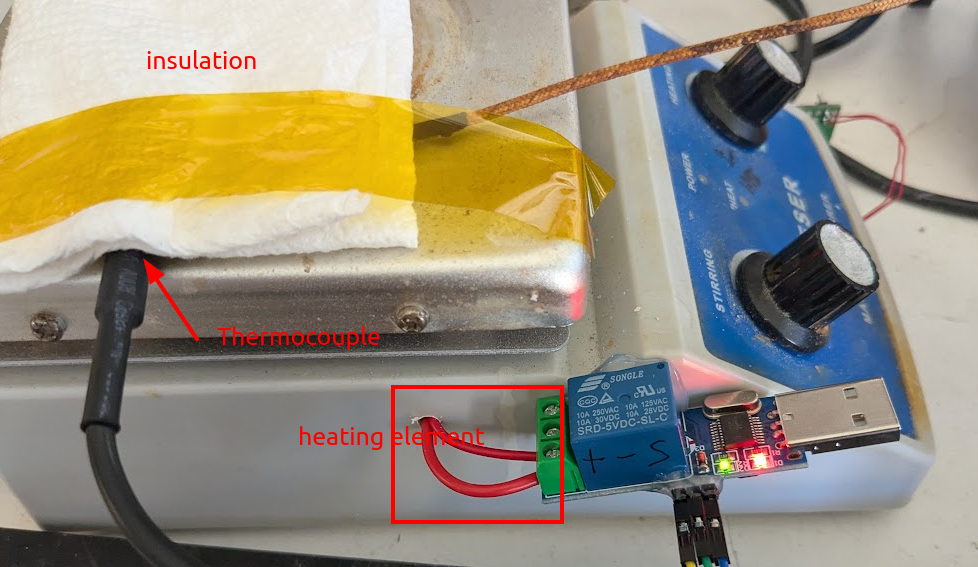
Here I have just wired the relay in line with the heating element:
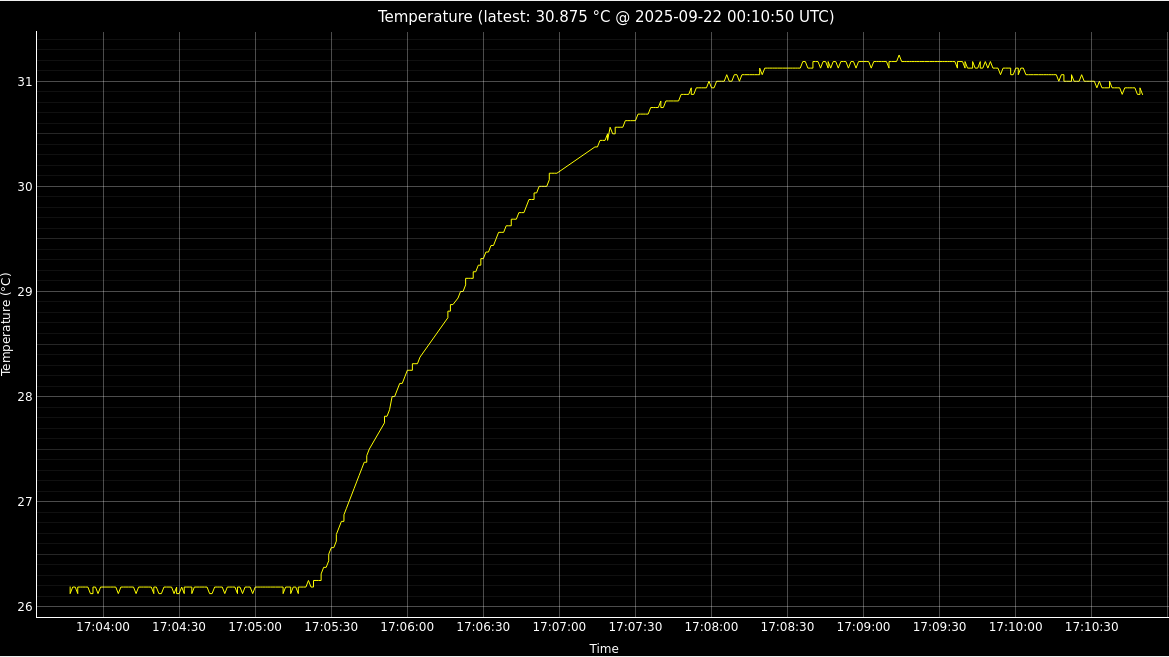
Time constant of bare hotplate
Here I taped the thermocouple to the hotplate underneath some paper towel for insulation, and turned the temperature on for a few seconds. The drift upwards is the thermal time constant for diffusion of heat from the element to the thermocouple:
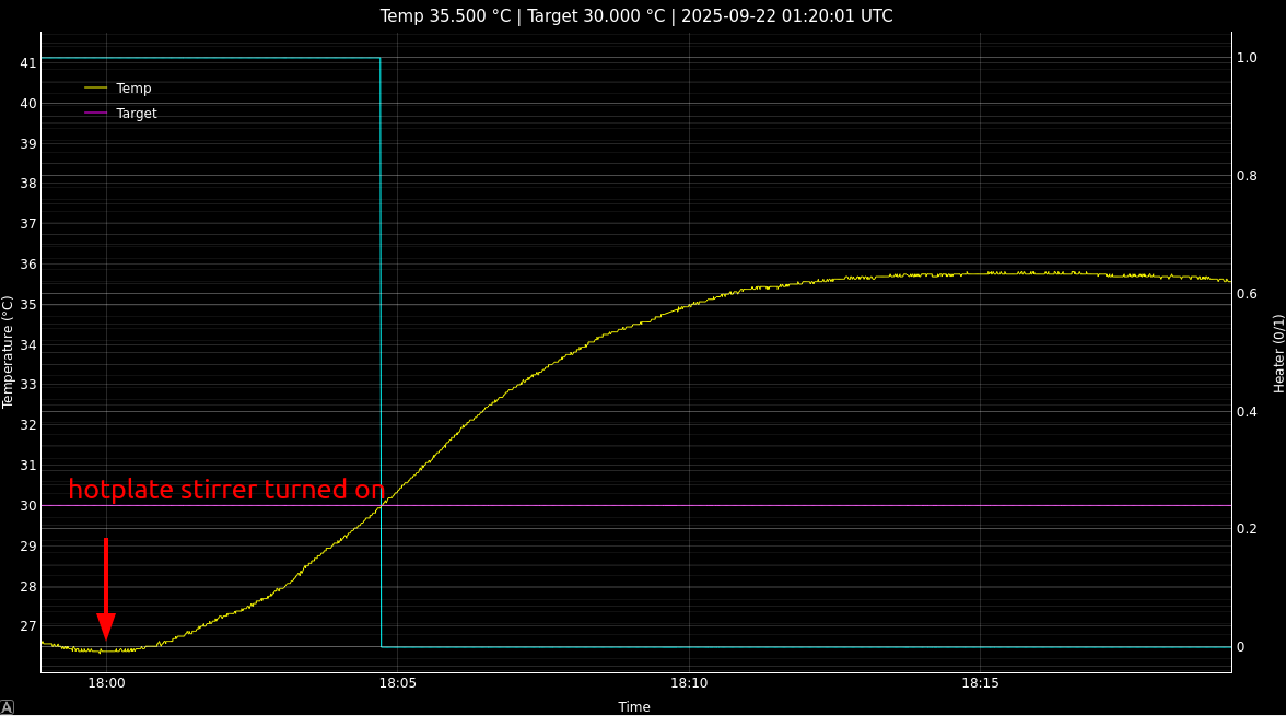
Working (bang bang)
here we have things set up so that the ESP receives a UDP packet that sets the temperature. Then the algorithm is just heater_state = temp < target_temp, so you get something like this:
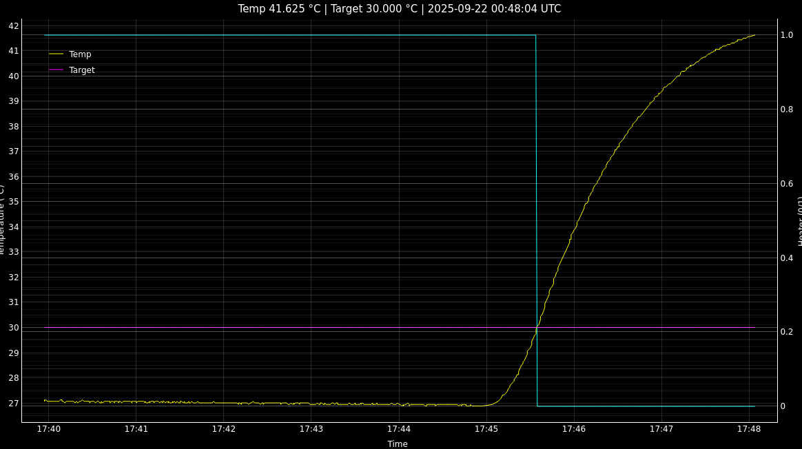
Where the relay turns off once the target temp is reached. There is massive overshoot here, but there also isn’t much thermal inertia in the system yet because this is a bare hotplate, not a beaker full of liquid.
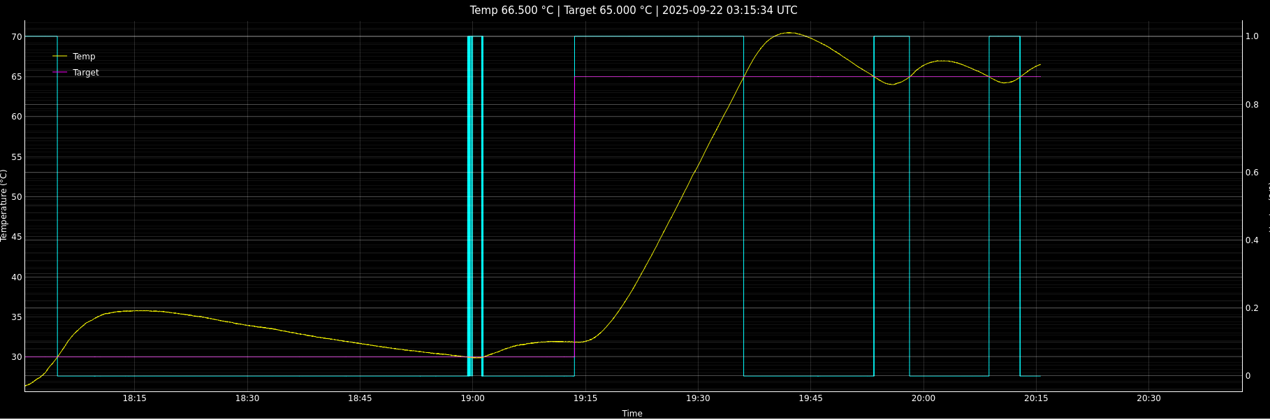
Beaker full of water.
Here is the result of a bang bang controller with the thermometer located outside the beaker hot glued to it with some paper towel as insulation:
I think the primary cause for this 5C+ overshoot is the lag between the liquid inside and the thermometer - i.e. it would be much much faster if I could immerse the thermometer.
Couple of oscillation cycles
Apparently it’s not so easy to have a thermometer immersed in a copper sulfate solution - it will corrode stainless steel and most metals. So it would be good to be able to figure out a solution where the thermometer could stay on the outside.
Stuck relay bug
Don’t really know how this happened. almost looks like the relay got stuck on or something. Would be nice to have a measure of the current. Anyway the temp only got to 94C, so that is another point against the thermocouple being on the outside.
overnight run #2
This is with
static constexpr float Ki = 0.1 / (20 * 60 * 10); // [duty / (°C·s)]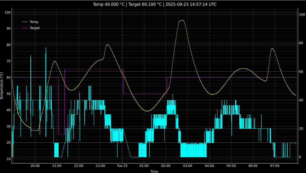
I term is still way too high I think…
Stuck relay bug again
I set up a run to hit different temperature points over the course of the day, and the exact same temperature runaway happened, only this time you can see it boiled off all the water, fortunately only just before I got home:
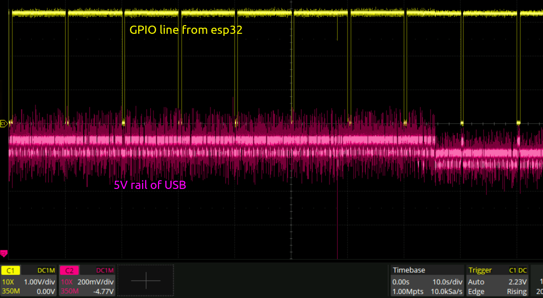
Here I was monitoring the 5v line of the relay as a crude current sense. When the coil is correctly actuated, the voltage rail drops a little bit.
On the far right of the below image, you can see that the rail is toggling up and down with the GPIO. And on the left it isn’t. This is because I gave the relay a good flick, which seemed to unstick it. So, the relay is no good for this application.
Different power control
Since the relay kept getting stuck, I decided some other way of controlling the power going to the heating element was in order.
Silly relay
…The less said about this the better
Triac
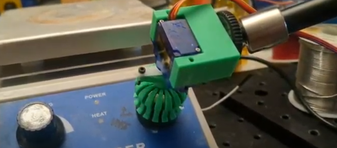
I found a old triac dimmer in the closet, looks like this:
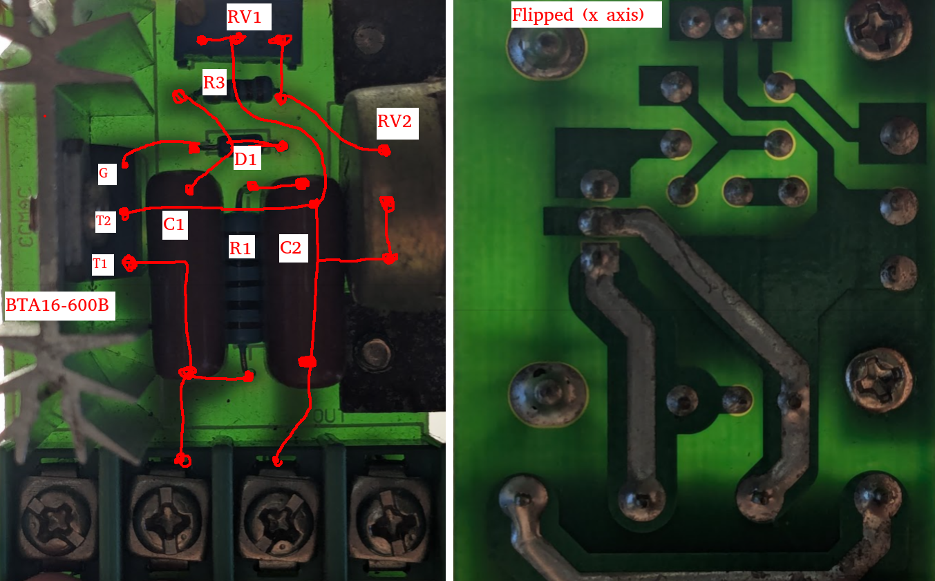
I believe this is the schematic:
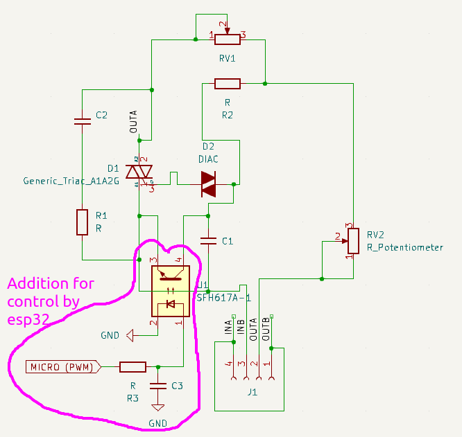
This is what the output of the system looks like:
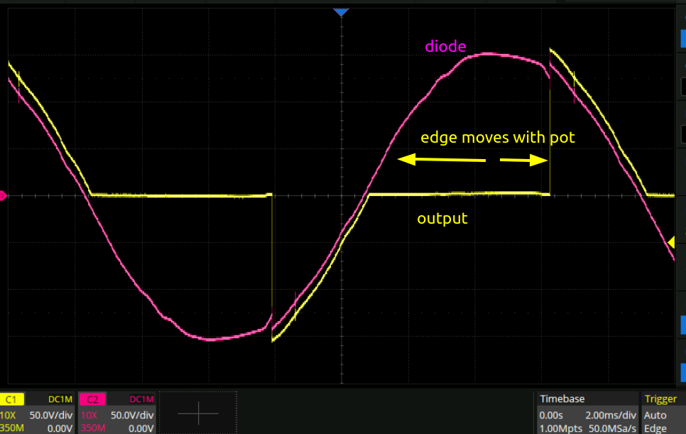
When I attache the above purple circled optoisolator though, only the negative half of the waveform is controlled, and the DIAC gets to >100C at high powers. I guess this is because the phototransistor is not symmetrical.
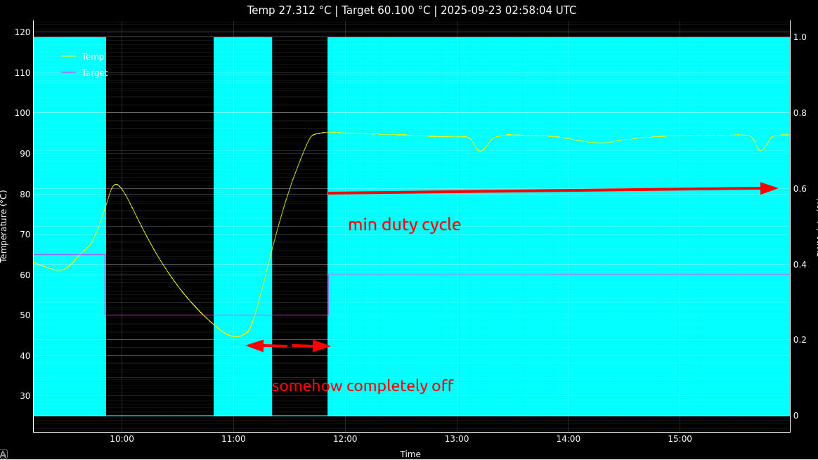
Off the shelf dimmer
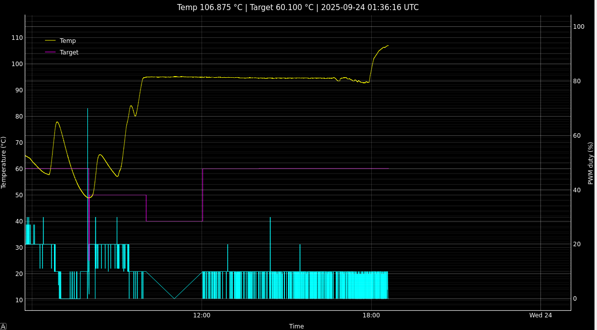
I bought this dimmer off amazon and it works just fine. In particular it doesn’t have the hysteresis problems that both the hotplate-stirrer and the pot controlled dimmer had. Now, I can actually control the temperature:
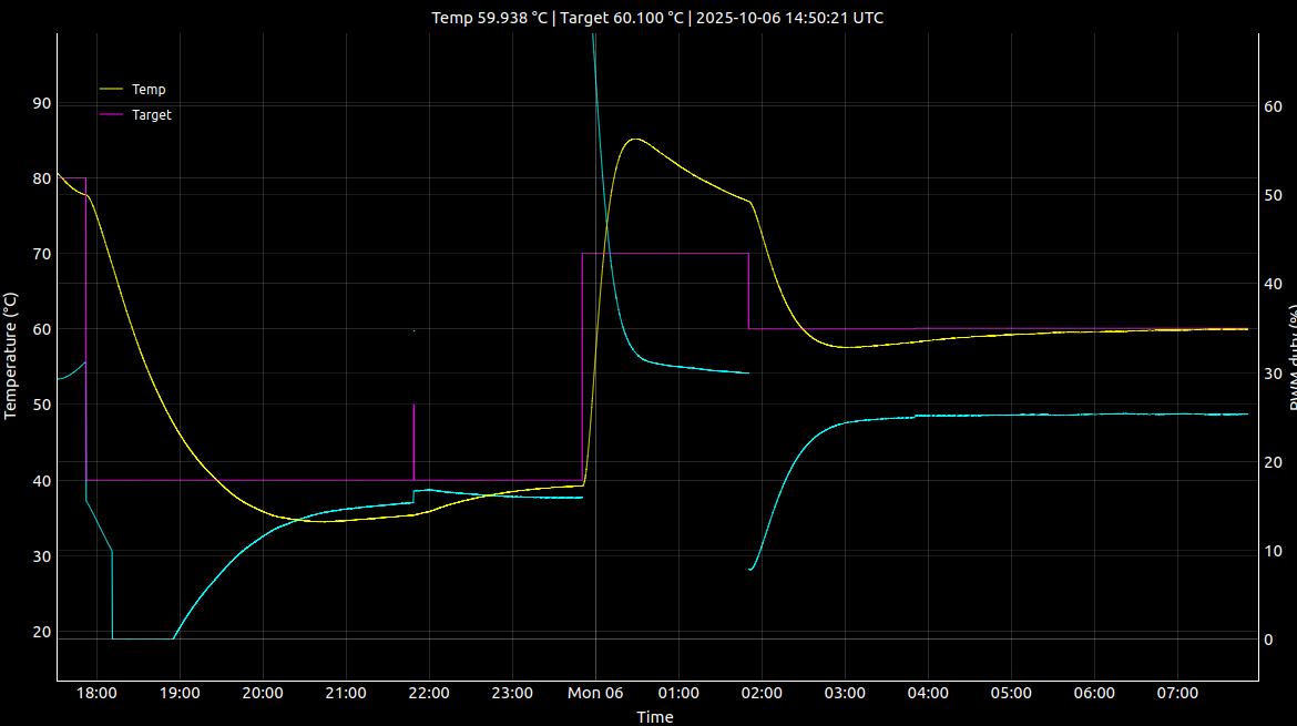
Though there is huge overshoot and it takes forever to converge. Though the temp ramps will happen over a few days, I think a settling time of like 6 hours might be a problem as it will affect the ability of the controller to reject disturbances over shorter timescales. We’ll find out I suppose.
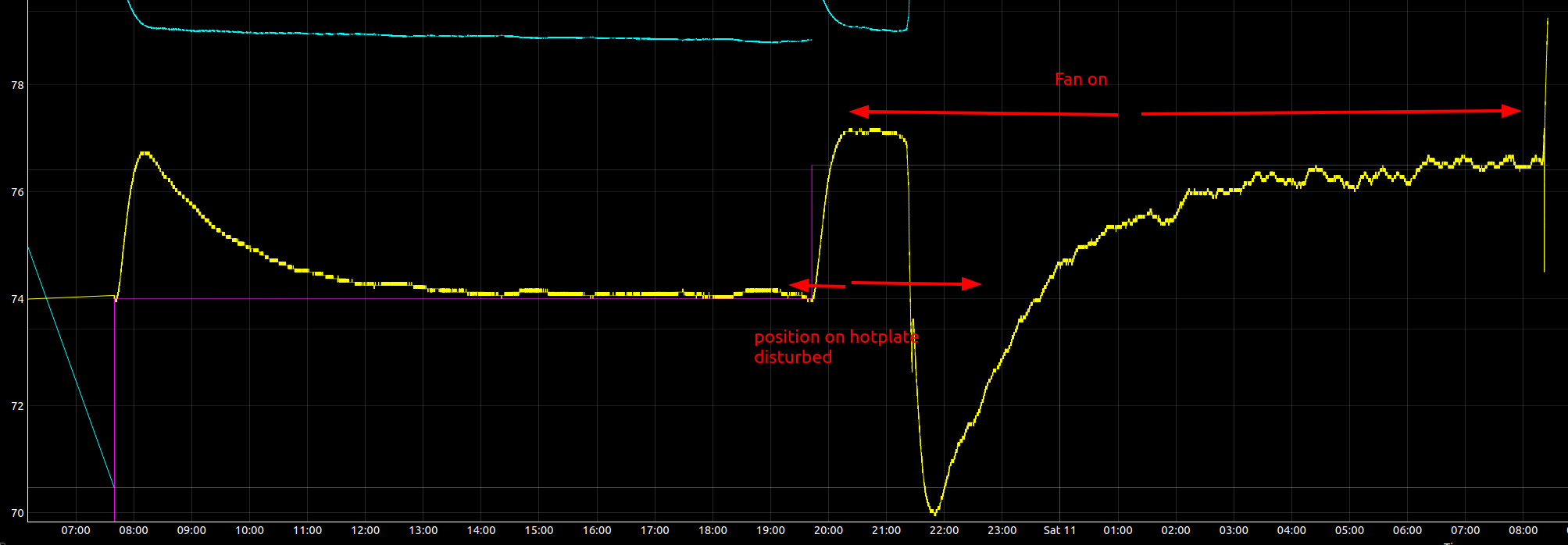
Disturbances
Here I left the system running in an empty apartment, and opened the door at some point to let cold air in.
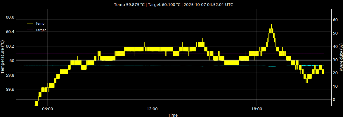
As expected there are a bunch of disturbances. You can see the duty cycle trying to compensate, but it isn’t really fast enough so the excursions are still significant.
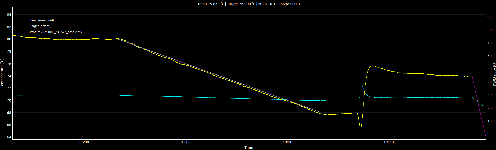
Temperature ramp
Fan on overnight