I had the idea of using a contact microphone attached to your belly to monitor digestive function. Here is the one that I bought:
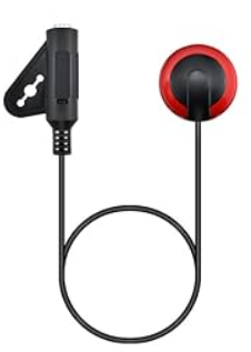
It has a diameter of ~20mm and an input capacitance of ~25nF.
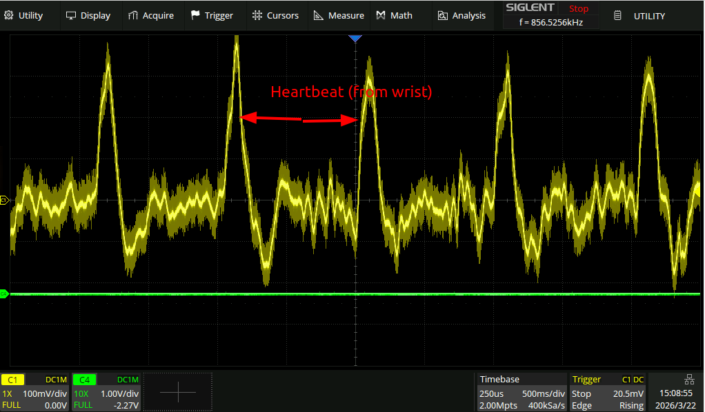
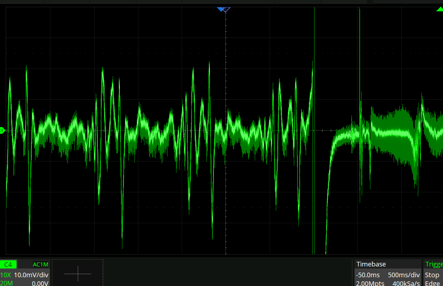
Hooking it up to the scope, I can see my heartbeat in my wrist quite clearly:
But, interestingly cannot see it in my neck. Attaching it to a headphone amplifier and routing that into headphones reveals some interesting stuff, but the headphone amplifier has an input impedance of apparently 17kR, which is too low to be able to pick up lower frequency content.
Time constant from scope
Here is the response to a well calibrated finger-press square wave input:
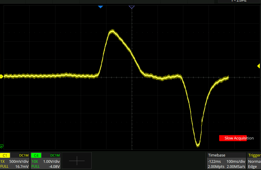
So with the 1Mohm scope input, the time constant is ~50ms apparantly.
High input impedance amp
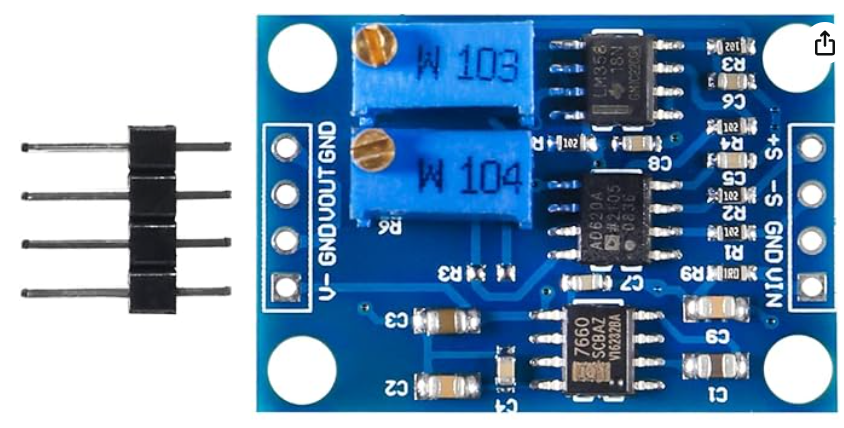
Per the above I figured I needed a high input impedance amplifier in order to be able to pick up the tummy rumbles properly. I got this one
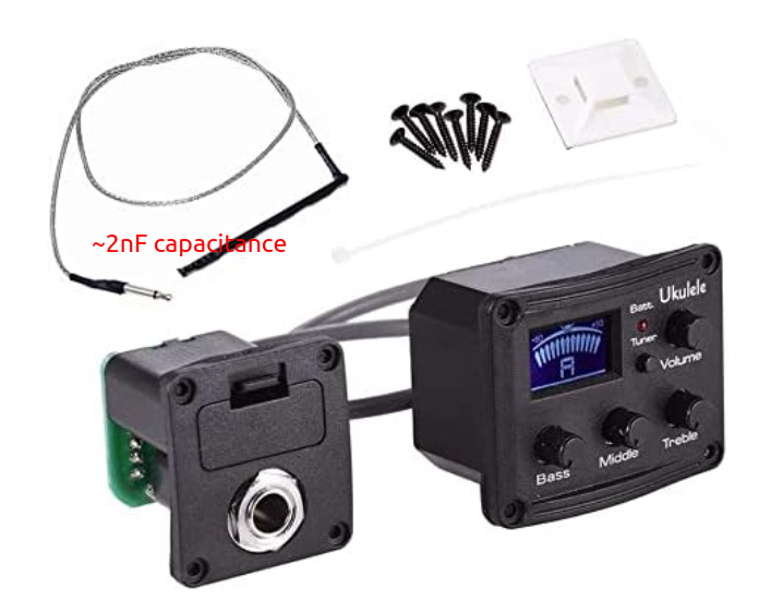
But after soldering on a 3.5mm jack attachment, powering it up, and figuring out I needed to max out the ‘bass’ knob, The signal looks horrible!
Here is the 20mm disk piezo again straight into the scope, showing the push/release signal:
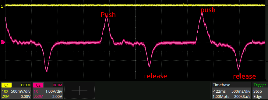
pretty clear AC coupled signal. Now here it is, coming out of the amplifier:
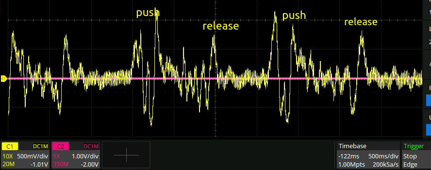
This is horrific. huge amounts of mains hum, and the signal is clearly wildly unstable for some reason. I note that the original piezeo pickup that came with the amp had a wire mesh shield all along it. Given how incredibly cheap it was, that was probably pretty necessary shielding and explains the mains hum on the disc piezo, but it does not explain the stability of the amplifier here.
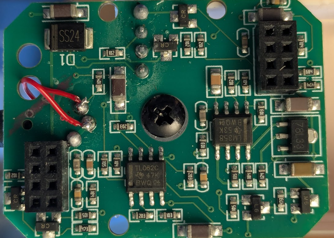
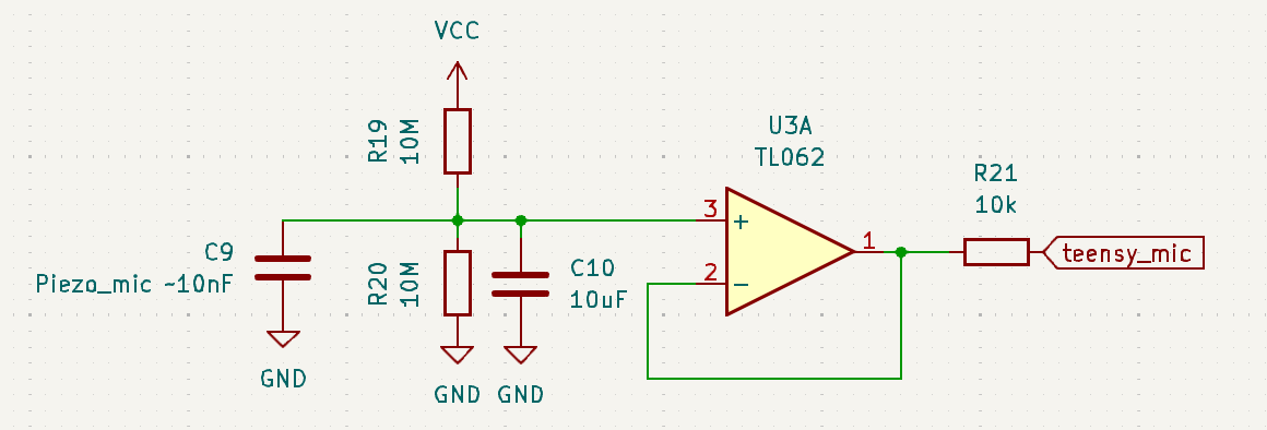
Perhaps ~10xing the input capacitance of the amplifier made it unstable. The input amp is a TL062c jfet input amp:
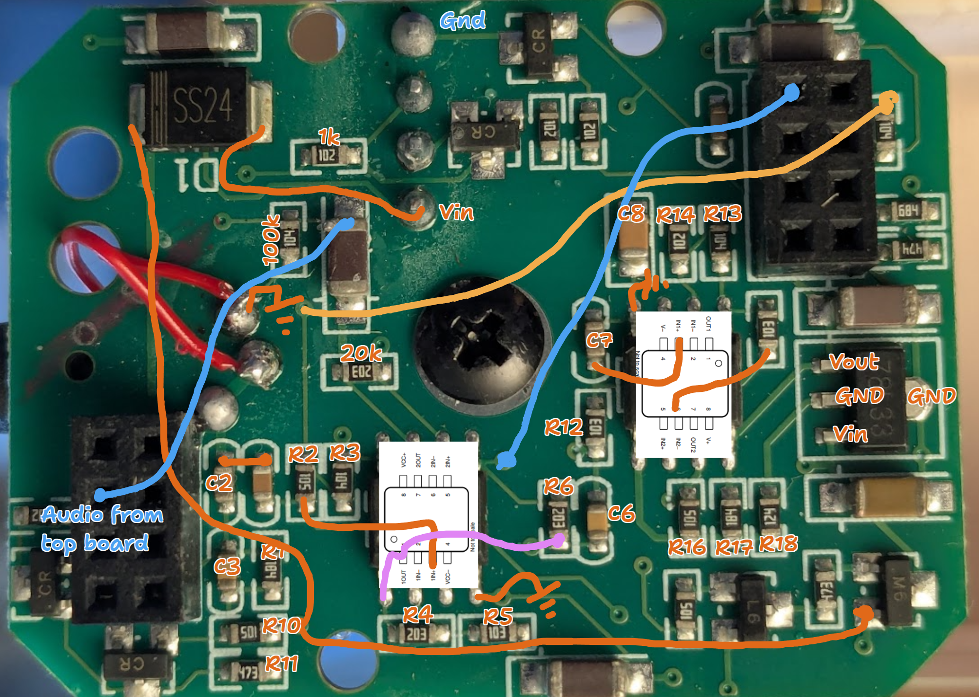
Schematic
Not particularly complete
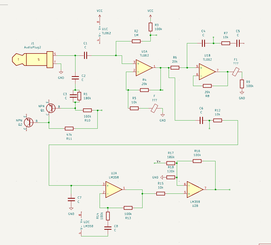
Crosstalk
The above board has a “feature” whereby the output is disabled and instead run into some tuner thing so it can tell you if your ukulele is in tune. To get rid of this I disconnected the output and then wired up the OUT2 of the LM358 through a cap into the output directly. No more problems here.
Now onto the recording. I powered the PCB off of a USB 5V rail, to which I also had a teensy attached with an audio shield. That way I can do actual recordings of the tummy rumbles and have a way of correlating food with rumble times and so on. Only problem is, there is: a) Huuuuge mains crosstalk b) Also a lot of crosstalk directly from the power supply. Asking mr claude to make a script that turns the CPU from max load to 0 at 300Hz results in a very loud noise in the headphones:
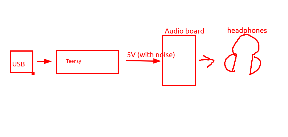
My vague understanding was that stuff like “power supply rejection ratio” of op amps was supposed to solve this, but clearly not.
…turns out that the ground side for the bias midpoint of the first op-amp was hooked up directly to the RING connection of the aux jack that plugged in. Because of my odd wiring, this output was disconnected and so the bias was pulled to one of the rails, which caused the strong coupling from the power supply rail. after shorting this line to ground, the noise from the teensy disappeared.
Output measuring heartrate again:
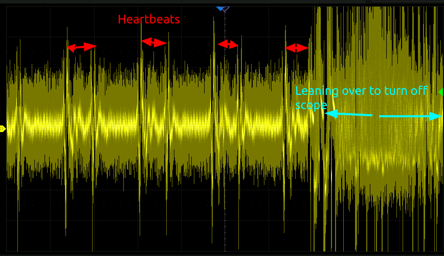
The system is extremely sensitive now, though it seems to have a huge amount of high frequency noise in it. this seems to be mostly outside the audible range so hopefully won’t cause too many problems. In the headphones, the heartbeat is accompanied by a bit of clicking so I think it might actually be saturating at one of the amplification stages.
At each stage
Directly measuring piezo:
Output of stage 1:
…yeah that’s already pretty bad. what’s going on??
This whole circuit has 4 stages of amplification for some reason. I think I just need to rewire it so it has one, and cut out all the funny business.
Simple buffer
Let’s rewire to try to get this, and see how it goes:
…nope, the power supply noise is super audible. I got claude to change the cpu loading so it ramped between 100 and 300Hz over a few seconds, which created a distinct siren noise in the headphones. This is what the FFT of the power supply rail looks like:
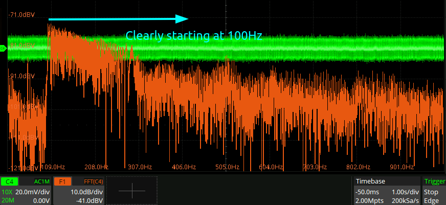
new amplifier, new problems.
I replaced the old guitar amplifier with a AD620 instrumentation amplifier from amazon:
This new one has two problems:
- It has a charge pump, and there is massive coupling between the charge pump switching and the output. The BOOST pin seems to have alleviated this somewhat
- There is much stronger coupling in this design between the power rail of the teensy and the output. The above mentioned triangle siren ramp is extremely loud. Putting a but electrolytic on the 5V rail and on the -5V rail did not help with this. Probing the rail with a scope suggessts there is ~20mV of noise. On this last part, it’s unclear to me if the issue here relates to the actual power supply, or some kind of grounding problem between the output of the amplifier and the mic ground of the teensy, since presumably the two are coupled.
Teensy audio shield grounding oddity
For some reason the MIC GND of the teensy audio shield is wired out to a GND pin on the header, and that pin on the CPU board is a regular power ground, resulting in the MIC GND being shorted to the power GND:
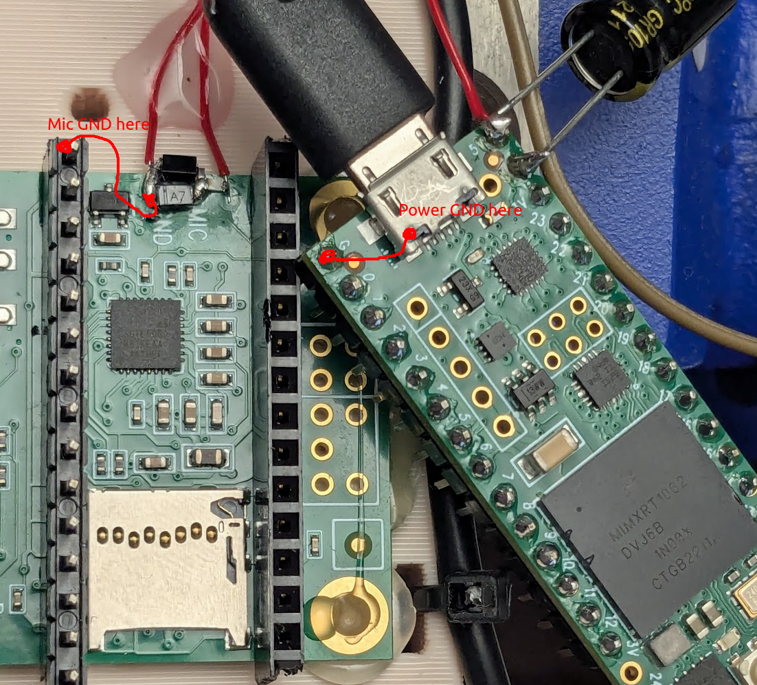
Seems like that might cause some issues.
Solution
The above AD620 eval board had a potentiometer and buffer to adjust the null point, the output of which went into the ref pin. The output of the AD620 is referenced to this pin, so power supply noise was directly coupled in. instead, the pin was shorted to the MIC ground which handily removed all the power supply noise.
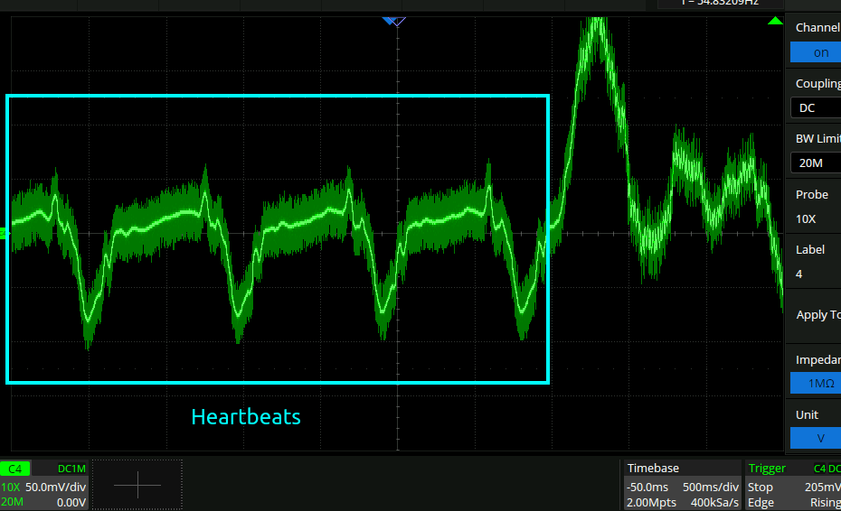
Now I can get these great plots:
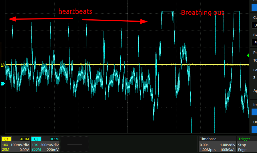
So far, I’ve been trying to keep the amplifier working down to as low of a frequency as possible. I’m seeing now though that this isn’t a great idea. the amplifier can easily sit at a large offset for many seconds, during which the output is completely saturated.
Recorded audio
I’ve now got things to the point where I can clearly hear tummy rumbles in the pickup mic, whilst sitting still. There are couple of weird things to iron out though
- Sometimes the audio signal fades out periodically. This may be due to heartbeat
- Noise from clothes and so on remains extremely high.
Here is a section of the audio signal loaded into audacity, showing the periodic fading clearly:
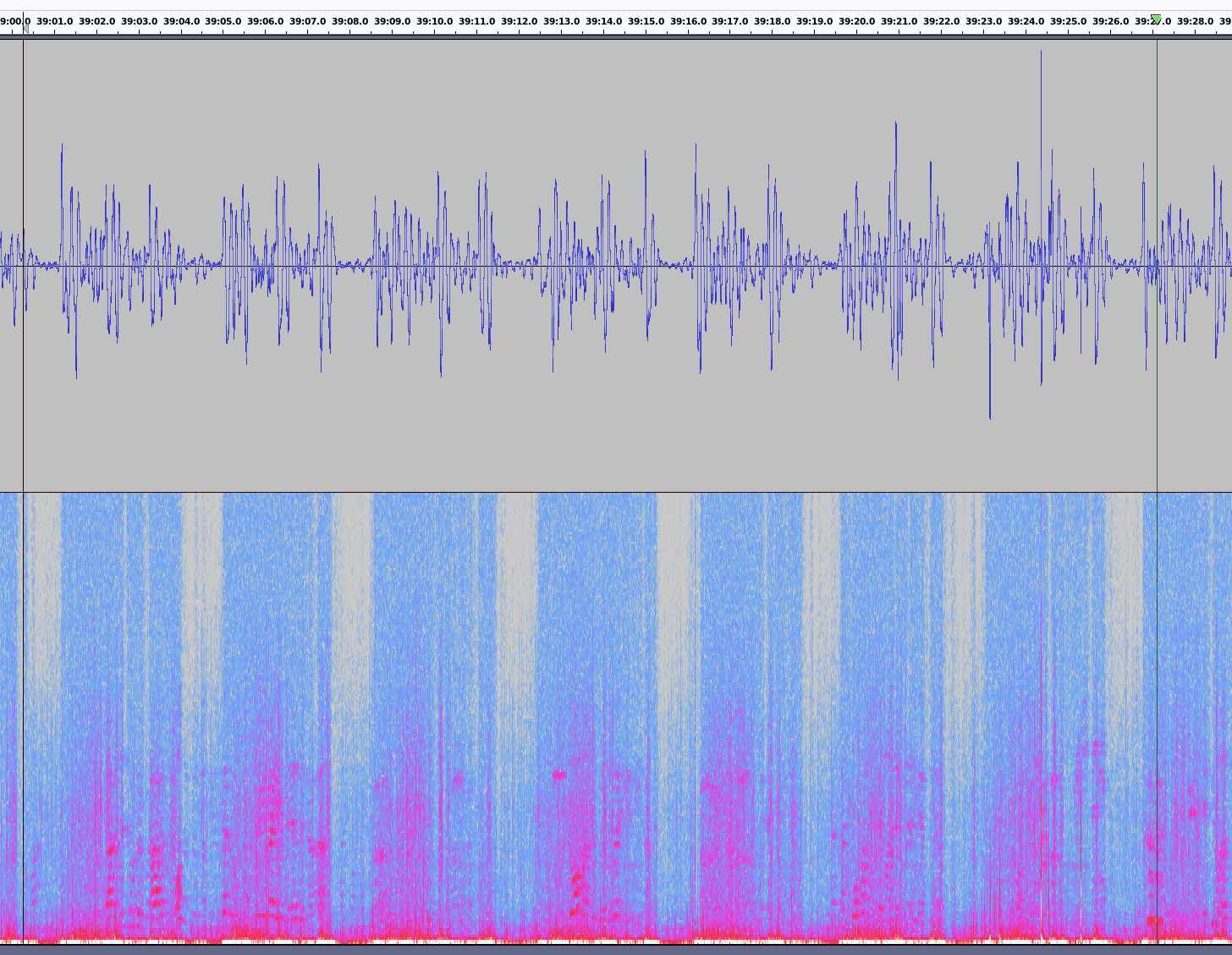
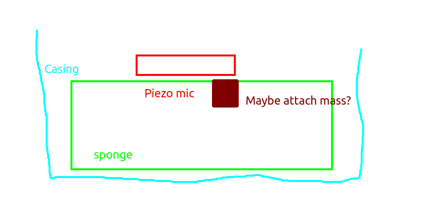
I can only assume that means that somehow the heartbeat is saturating some part of the pipeline. This is more or less what the circuit looks like now, from my best guess as to what is in the amazon schematic.
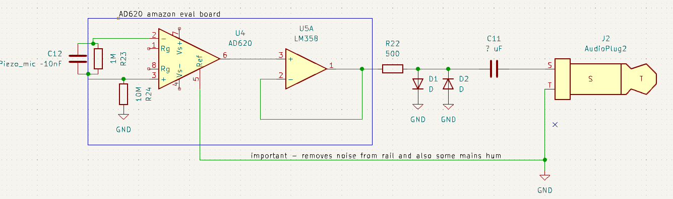
so it’s:
- The long time constant of the RC piezo mic-R23 discharge resistor. I tried to adjust this to a <1s time constant though.
- Some other DC drift in the sytem, perhaps from the 10M from the piezo to ground.
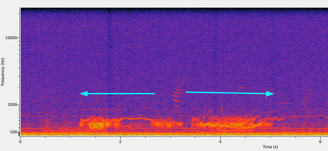
- Nonlinearity in the piezo mic. If the piezo mic is compressed by my heartbeat, then perhaps whilst it is compressed then it is less sensitive. If you look at the above spectrogram though, the white noise also reduces which is presumably amplifier noise, so I think this is unlikely. I can’t think of anything else that has a >1s time constant like that.
There is also some DSP processing happening in an attempt to de-emphasise the very loud heartbeat signal that I had claude add:
    codec.enable();
    codec.inputSelect(AUDIO_INPUT_MIC);
    codec.micGain(20);
    codec.volume(0.45);
    codec.eqSelect(GRAPHIC_EQUALIZER);
    //                         115Hz  330Hz  990Hz  3kHz  9.9kHz
    codec.eqBands(              0,     10,    10,    10,   10);
    codec.lineOutLevel(13);
Live streaming audio over USB
Downloaded friture which is pretty good. Here is a trace showing the piezo attached on the last rib of the ribcage:
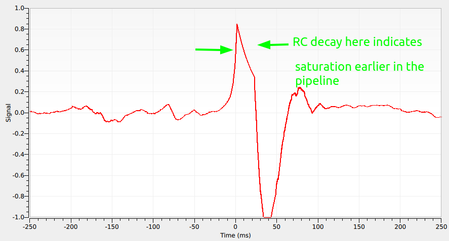
This is a heartbeat, and you can quite clearly see that the pipeline is saturated in at least two places. The clean noise-free RC decay there indicates that somewhere is hitting the rail, and then it hits the actual rail of the microphone at the bottom.
Just turning the gain potentiometer on the AD620 down gets rid of both saturations. The RC decay saturation is from the diodes clamping the rail, as determined by probing on top of the diodes. it’s a bit surprising though, because the mic gain is also set to 20dB, and you would think that clamping at +/- 0.6v (1.2vpp) would mean the mic would need 0dB of gain.
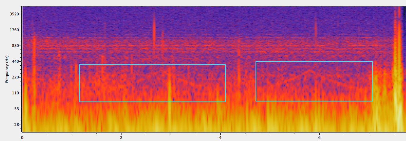
Here is the spectrogram of an exceptionally loud rumble:
New piezo mic
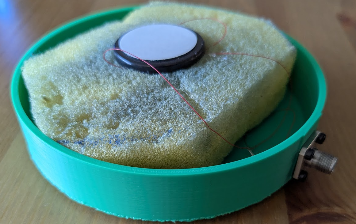
Hopefully this should isolate it from external vibrations somewhat. If you think about it though, if the piezo disc was massless, and suspended from external forces but still stuck onto the stomach, then it wouldn’t measure anything because there would be no way for the piezo to be squeezed when the stomach rumbled upwards:
It’s only the inertia of the piezo disc, and the loading from the sponge, that cause it to be compressed and generate a signal. So maybe attaching a large-ish mass to the mic would help with getting a better signal.
So I added two copper plates with a total mass of 41g:
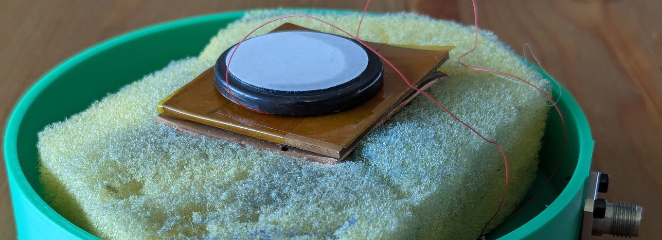
This increased the signal by quite a bit it seems, but did not seem to increase the isolation of the mic from interference from tapping on the casing and so on. I still have this huge noise/heartbeat band at low frequencies too:
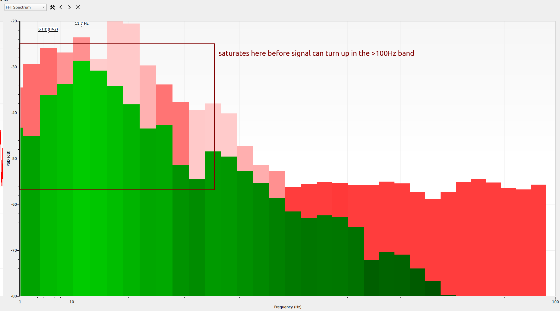
That saturates before anything interesting can be found at the higher frequencies, so I think that needs to be reduced down a bunch first.
Mic rev 2
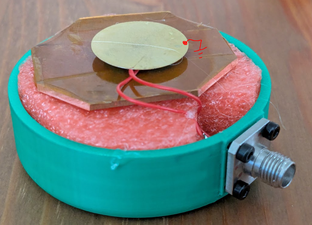
I noticed with the previous revision of the mic that I needed to touch the ground of the connector to get rid of mains hum, so on the next revision I set the brass plate that is one side of the piezo disc to be against the tummy.
Specter of power supply noise
I left in the previously mentioned ramp up and down, and you can now actually see it just barely:
If you know what to listen for you can also hear it.