Using OpenFOAM and the literature gathered from here Mr Claude furnished me with this simulation of a small pulse jet:
Net thrust 0.09N, lovely.
Thrust on a plate
Since the net force on the pulse jet body at 0 speed is quite small as a result of the pulse jet inlet facing in opposition to the outlet, we can do in the simulation what was done in the real lockwood paper, which is place two plates at either end of the pulse jet and measure the forces on those plates. Perhaps this could be done non-physically in the simulation but let’s do it ‘for real’ here with a real plate.
Puff hitting a plate
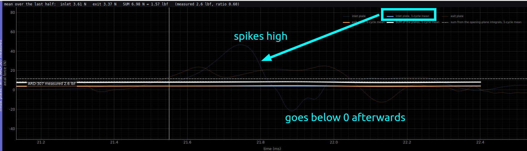
An interesting observation: In the sim we can see that the force on the inlet plate spikes super high and then shortly afterwards goes negative, kind of like it’s “AC coupled”:
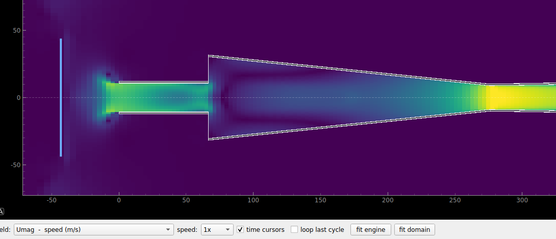
Velocity showing the puff of air about to exit the inlet:
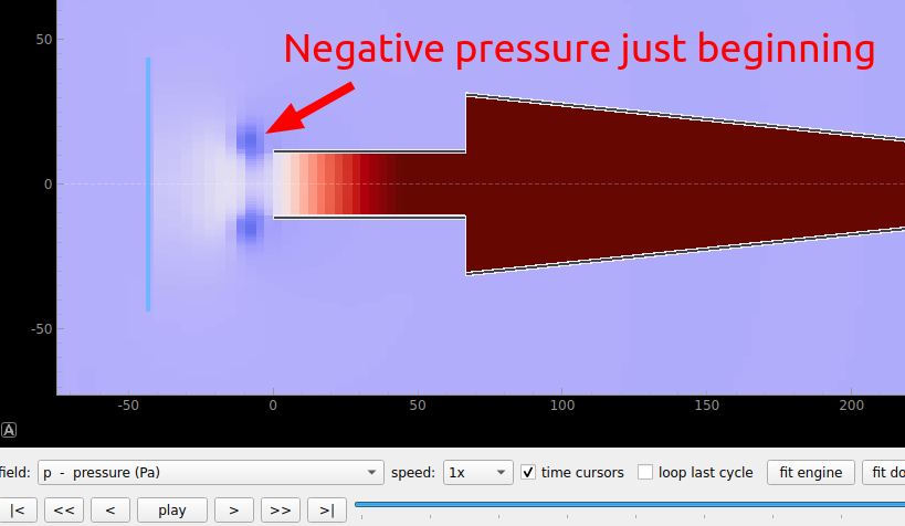
Colored by pressure:
Here it is when there is peak force on the plate pushing the plate away from the pulse jet:
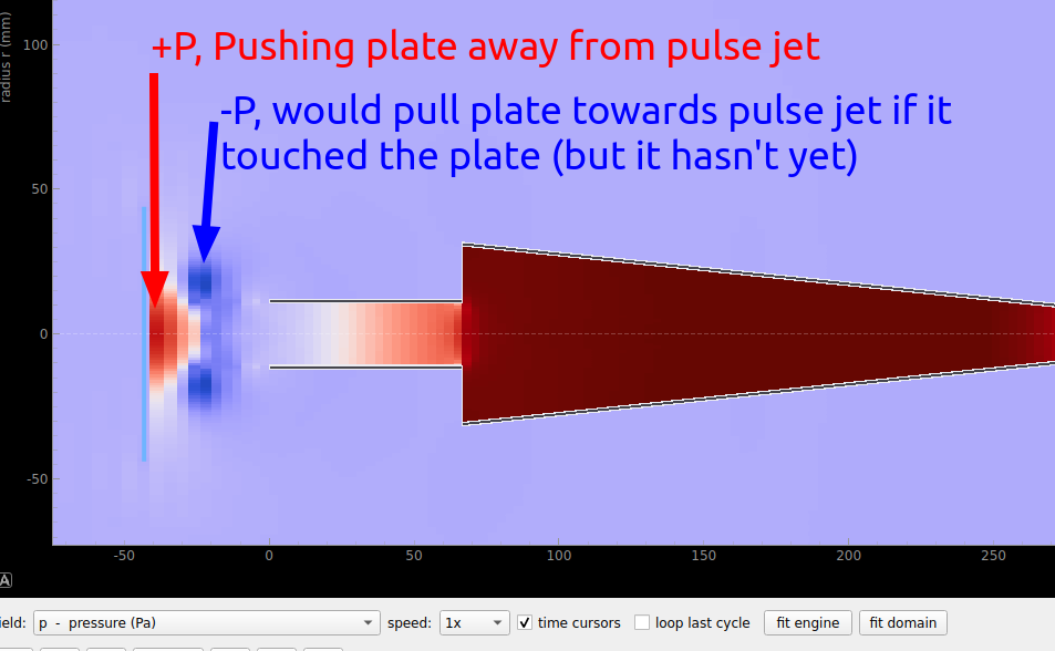
And here it is when the force is swung in the other direction and is on net pulling the plate directly towards the pulse jet:
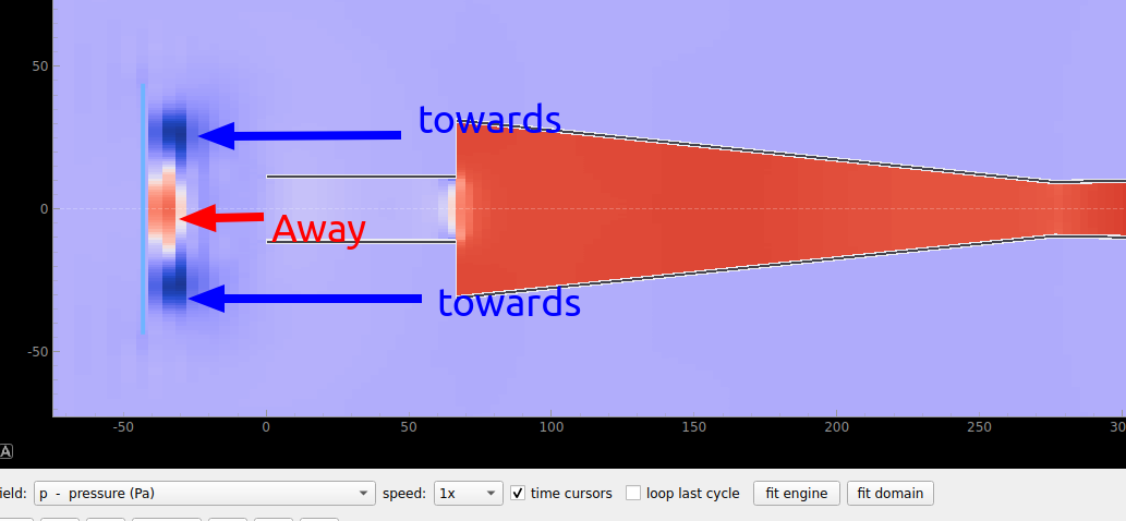
These curling pressure pulses look real but not really related to how a pulse jet would work in normal operation, where the jets of gas don’t hit a plate. I don’t really understand how this method of measuring thrust used by the lockwood paper is valid.
Optimisation of current pulse jet, HH-M2
This is claudes best guess of what the simulation should look like with the pulse jet that I’ve actually built, and which is called HH-M2 in the lockwood papers.
This is the temperature layer:
The CO2 layer actually also looks pretty good, but something here is a bit off, the CO2 seems to diffuse away into nothing in the exhaust. I feel like that wouldn’t actually happen:
Actually, why am I pasting gifs? claude, paste the whole app here.