Loop gain
After deciding last time that the loop of the VCO needed to be DC couples to support a mismatch in the frequencies of the RF and LO signals the art of electronics delivered with this as a good amplifier topology :
Transclude of differential.asc
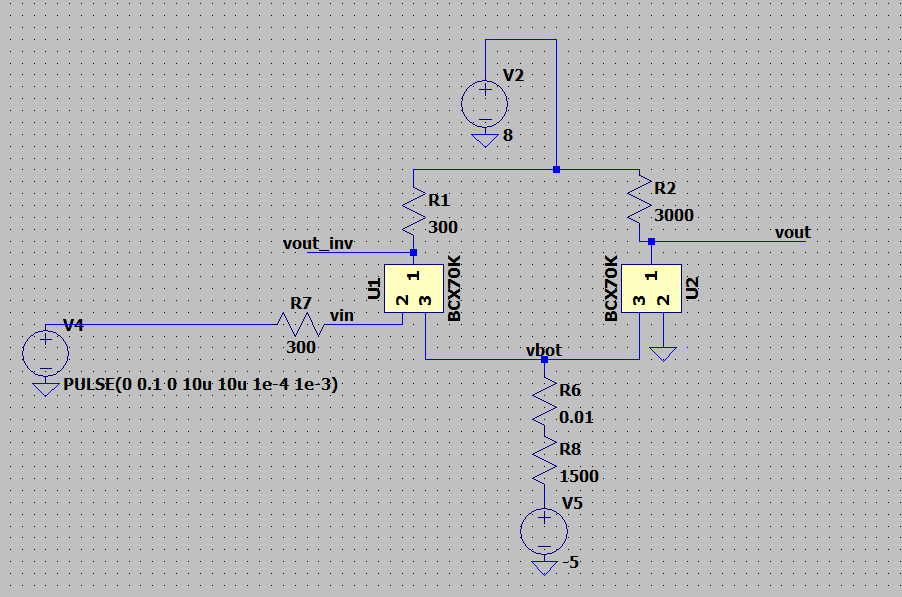
which is just a fully differential amplifier with one end grounded. Hopefully the negative rail can be removed in the future, perhaps by floating the mixer since the two inputs to the mixer can obviously be AC coupled.
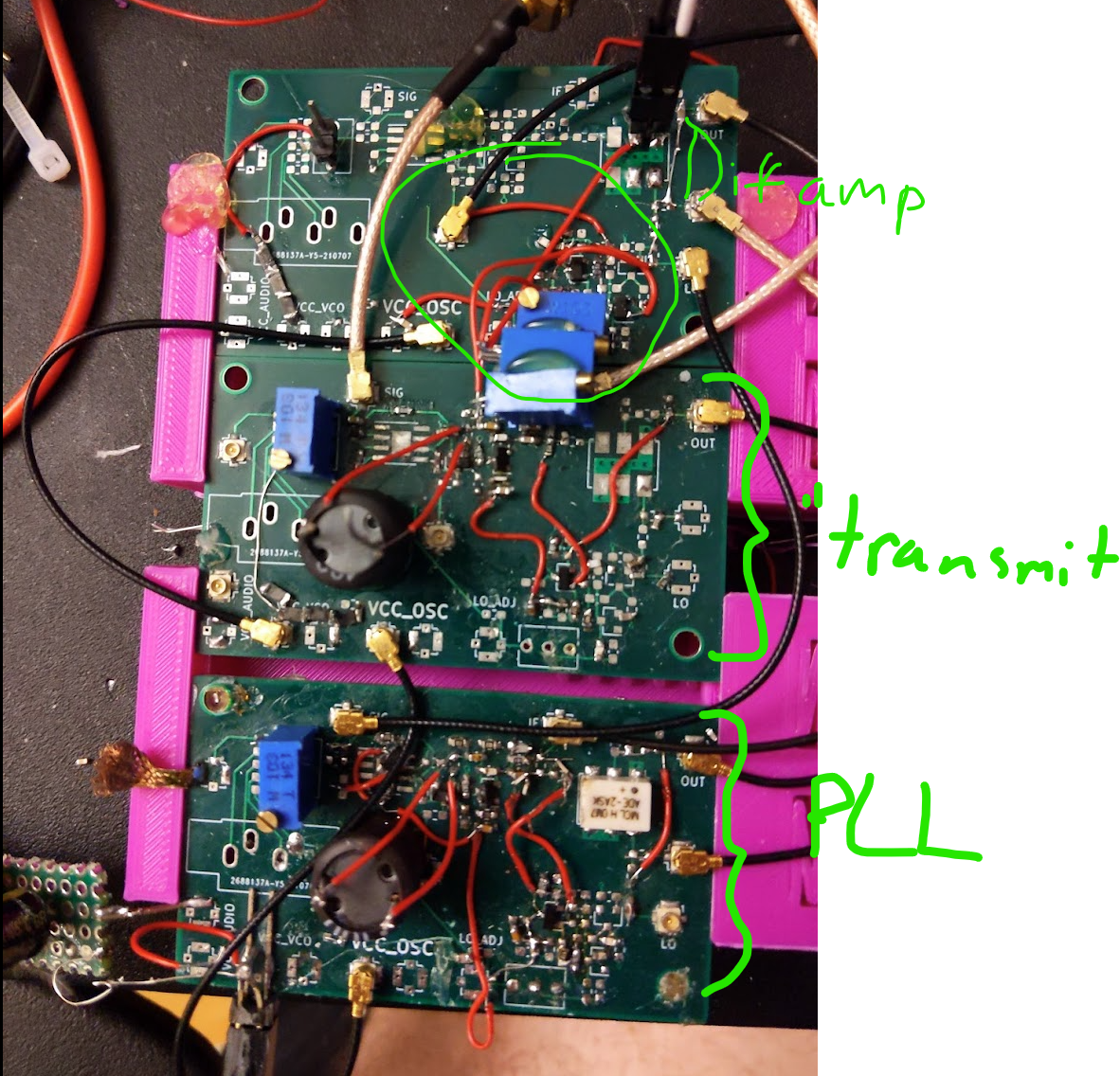
The above resistor values didn’t seem to work so I put in a pot for R1 and R8 in the above LT spice file. The board looks like this atm:
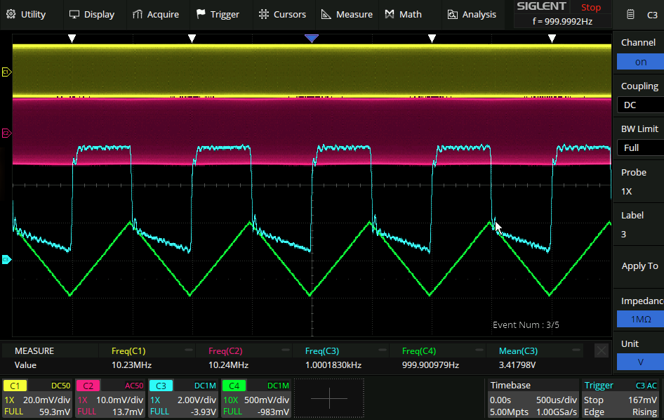
And now the loop filter has a lock!
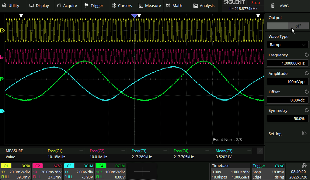
Channel 1: VCO Channel 2: “Transmit” Channel 3: output of PLL control loop Channel 4: AWG of the scope modulating the VCO It only works modulating by up to ~200mV on the transmit side, after that the PLL seems to lose its lock:
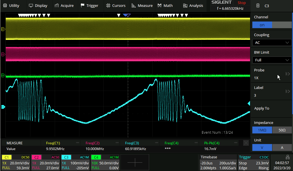
The chances are that this is due to some combination of not enough gain or not enough bandwidth on the part of the differential amplifier. I was able to improve things a bunch by twiddling the two potentiometer knobs of R_e and R_c and given that this is a 2D search space it seems unlikely that I’ve hit a local minimum. Nonetheless I think the next step is find out what the actual values are, pop them back into LT spice and try and get some more modulation bandwidth. More modulation bandwidth is good for two reasons - it uses more bandwidth in the air (better SNR) and also it means that the VCO control voltage needs to be higher, perhaps enough even to mean that no post amp is needed.
Aside: I hit the diff amp with the hot air gun when it was marginally unstable and it didn’t seem to do much, so that’s points towards thermal stability I guess.
Phase margin measurement
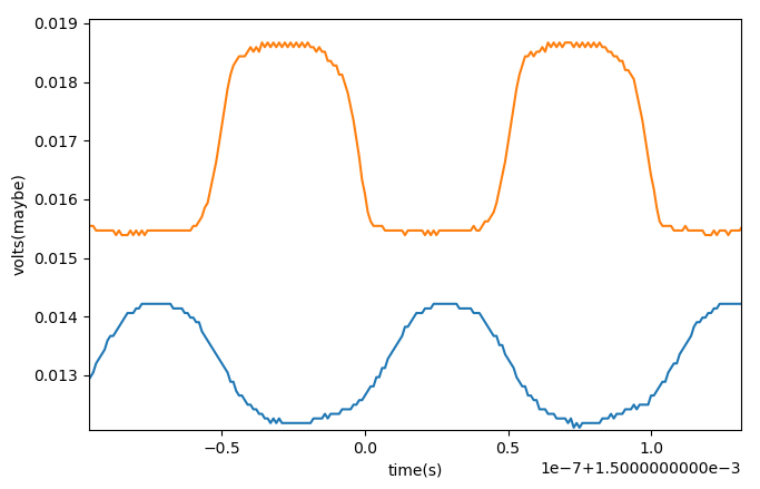
Or at least I think this is phase margin. We seem to be running out of it, in any case. Here is the raw data collected on the scope:
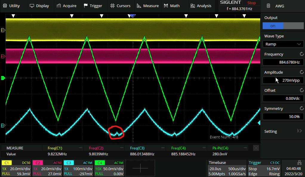
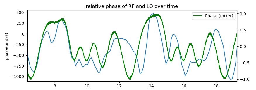
This is right on the edge of stability. note the little blip at the bottom where the PLL is beginning to lose its lock. Pulling the data down from the scope, we measure the phase of the signal directly to look like this:
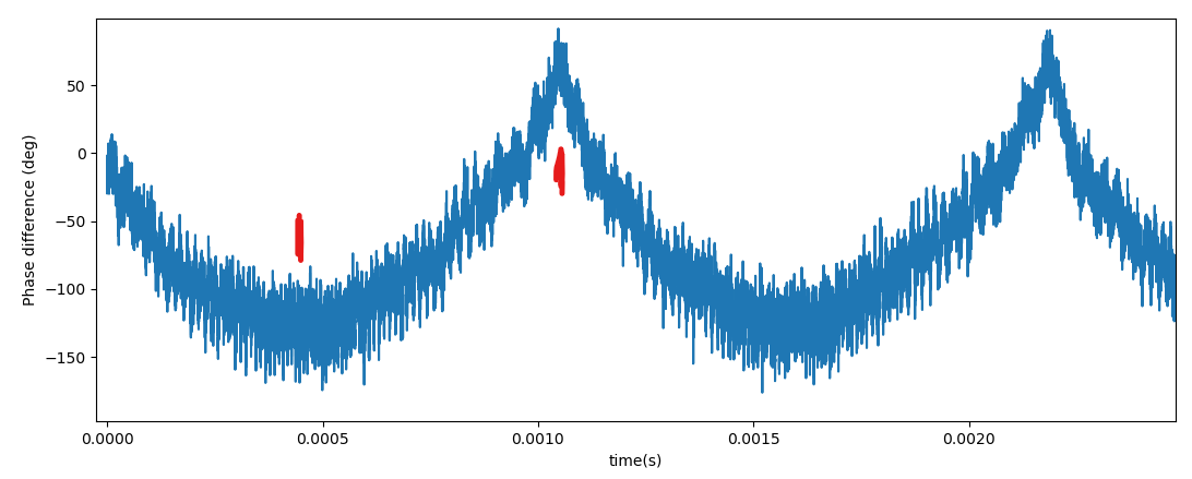
Taking at close look at the best and worst portions (in red above):
| Minimum phase (~-120deg) | maximum phase (~50deg) |
|---|---|
 |  |
| …Obviously the absolute values aren’t so crash hot here but directionally this seems to be correct: The reason the PLL loses lock is because there is too much phase shift. Pre-registered hypothesis: this is because when messing about with the pot I destroyed the bandwidth. |
Loop gain optimisation:
State as of the above pics: Emmitter resistor: 3.4k Collector resistor: 3.4k Interesting! I had no Idea at the time that I was optimising them I had converged on equal values, wonder why that is. The “transmit” VCO is at 1.4V and the PLL VCO is at 2.9V. Odd that the control voltages need to be that different, though it is quite possible that the circuits are a bit different. It’s possible that since the two varactor diodes are in such different regions of their capactiance(voltage) functions this is what’s generating the mismatch. https://www.nxp.com/docs/en/data-sheet/BB201.pdf
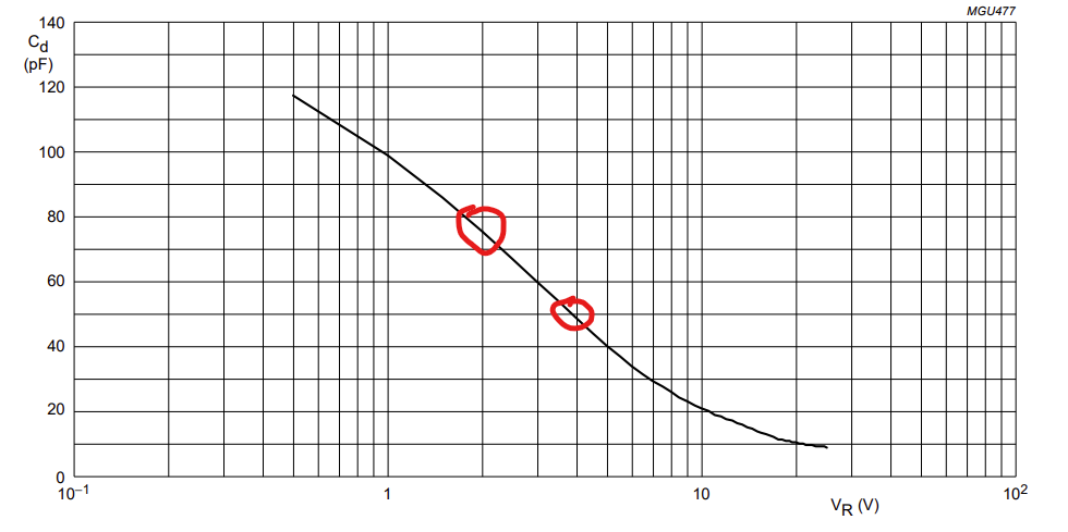
Maybe there’s something about the difference in the slopes of these two graphs or somesuch, idk.
But wait, nothing works
Actually it seems that the above stuff may have happened when one of the connections on the circuit was broken. Here is the circuit attempting to do feedback with the circuit “operating as intended”:
(note the vertical scale) Here Ch4 is the mixer phase difference and CH3 is the control voltage of the PLL. I think somehow a 80deg phase shift has been introduced here. The behaviour of this circuit is that as you adjust the emitter resistor of the differential amp to adjust the DC setpoint of the output (and thus the PLL center frequency) you can tell that the control loop is kinda squishing up against its limits until it “pops” out the other side. idk if this diagram helps explain:
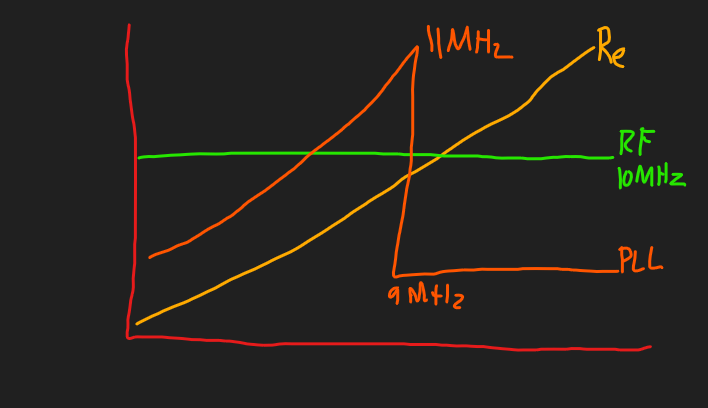
(Re is independant variable, PLL is dependant variable) This mercury-under-your-thumb behaviour occurs when the output of the differential amplifier is taken from the positive or negative end of the scale which I feel is a big clue but am not sure what it means.
Observations and thoughts on required bandwidth
Aside from the possibility that everything is hooked up backwards it seems that something is clearly acting out of phase here - positive feedback is being created. The frequency response of the VCO seems do be dominated by the RC of the 100k resistor and the 50pF of the varactor diode, so I changed that to be 10k to spice things up. It spiced them up alright, but not in a good way.
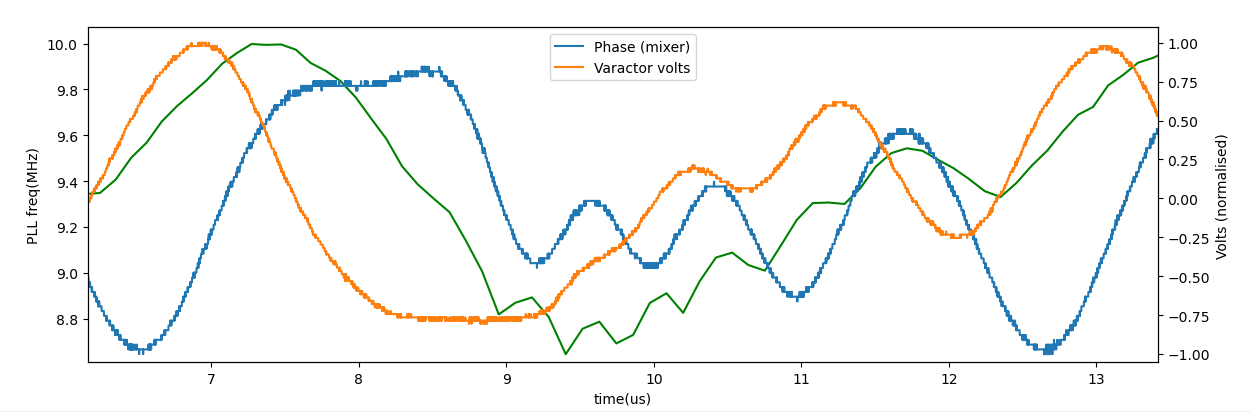
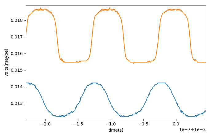
(Green is the VCO frequency sorry) So what is happening here is the phase signal (Blue) feeds into the Loop filter (orange) which then affects the PLL frequency (green). At these frequencies (300kHz difference) there is clearly quite a bit of lag happening. The phase as measured by the mixer vs digitally seems not to show much latency per se, although there are definitely discrepancies:
I think those are mostly due to the method of calculating the phase though , which assumes a constant frequency.
So the next step is to slow stuff down so that the VCO has enough time to react to the output of the loop filter. Perhaps just increasing the resistor that feeds the varactor diode would be enough to do that:
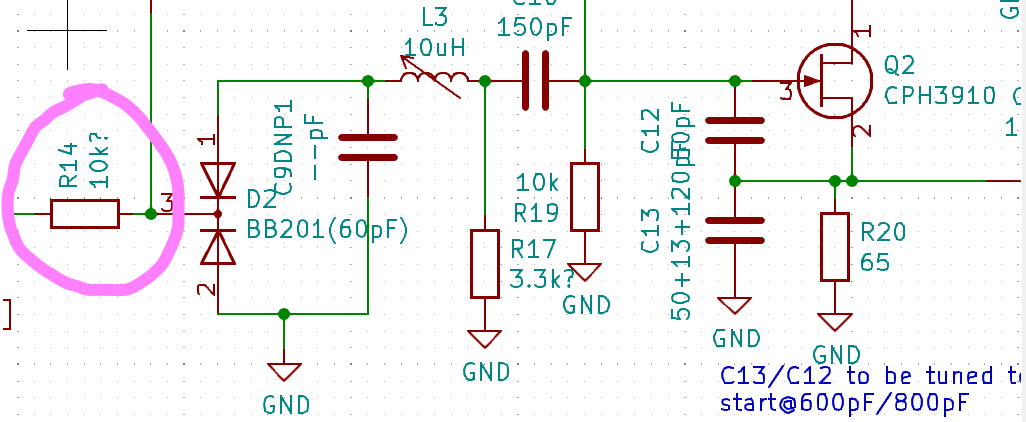
Let’s try 10MOhm! That should give 1 / (2*pi*10e6*50e-12) = 318Hz(!!) of bandwidth.
Here’s what that looks like:
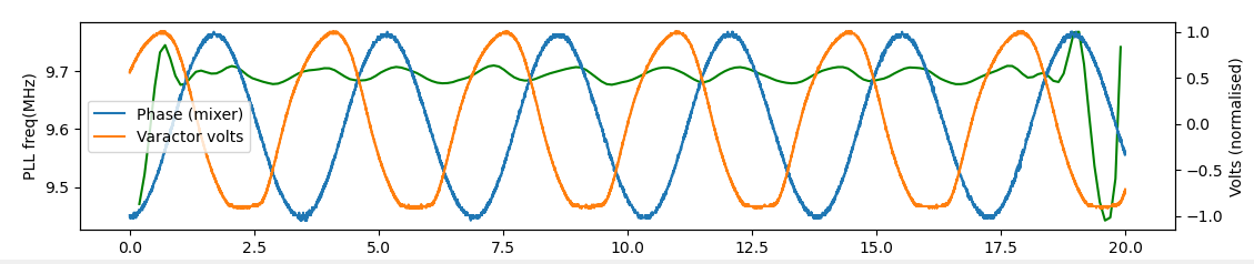
I had to filter the RF output but I think the result is correct. So essentially what is happening here is that the VCO is basically seeing the average voltage at the output of the loop filter at all times. If the average voltage tends not to reduce the frequency error, then things will just stay as they are. I guess that’s not what we want to change here, then. The latencies that exist in the system are:
- Applied volts → VCO frequency
- VCO frequency → Phase measurement
- Phase measurement → Applied volts So if these latencies add up to greater than the difference in frequency of the modulated and PLL signal, things will be wack.
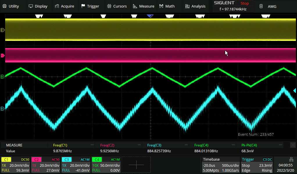
Quick weirdo observation
This is with a 10meg resistor feeding the varactor diode and a ramp wave being fed into the RF input. weird. I think this arises because the signals have a tendency to injection lock anyway, and this is just a special case of that where they remain injection locked but at different relative phases depending on if the frequency is ramping up or down.