So it turns out that my oscilloscope has a Bode diagram feature, and that all oscolloscopes these days do too. Who knew?
Passive filter
Here is the passive loop filter that’s supposed to get rid of all the wacko harmonics around 10MHz:
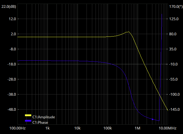
Take a look here Designing a loop filter for the actual construction. I imagine the “gain” in this filter comes from how things aren’t remotely 50R, and so the absolute level here isn’t really right. The flatness of the phase should be, though.
Active filter
Adding in the differential amplifier here: Loop gain and the response looks like this:
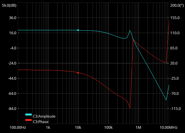
measurement looks a bit cooked at the higher frequencies there. Considering I wanted to do at least 100KHz of FM swing here we probably need to increase the bandwidth.
VCO bandwidth
We can’t really do a frequency sweep of the VCO in quite the same way, but we can do a step response:
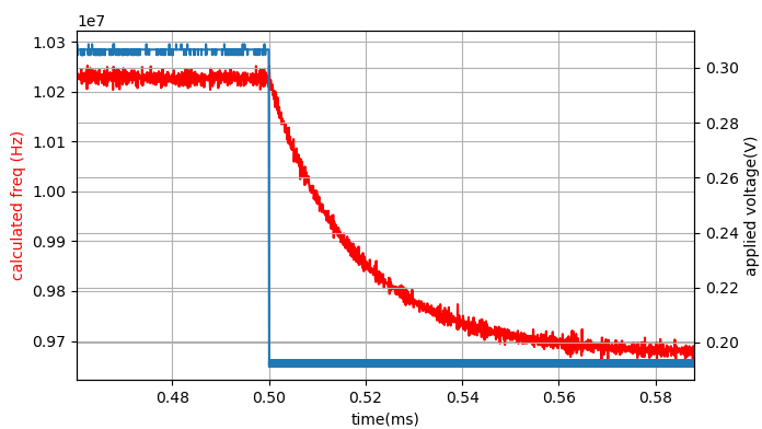
So the 90-10 fall time here is 0.35 / (0.5483 - 0.5012) = 7.4KHz - Not really that great! Prolly should have measured this some time ago. That was with the 50k resistor talked about here Observations and thoughts on required bandwidth. Changing that to 10.7k Gives this:
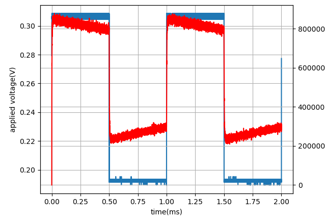
which is 0.35 / (0.5055 - 0.500) = 63KHz: Better! Although there is a weird frequency ramp on top of that which is a bit worrying. But you gotta pick your battles. Now I think what we want to do is have a lowpass that’s significantly below that - say 20KHz and apply that to the output of the IF. That way the VCO is guaranteed to be a lot faster than the loop filter.
Slow down the right thing
Adding a 2.2nF cap in the diff amp to slow things down gets us this waveform:
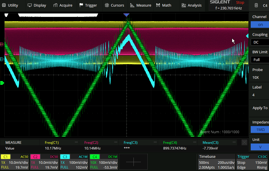
So close! It looks like the PLL can’t keep up for some reason and looses the lock. Blue and green are on the same volts/div, although blue is AC coupled. Adjusting thing slightly we can see that when the PLL loses the lock the error signal is around 50KHz:
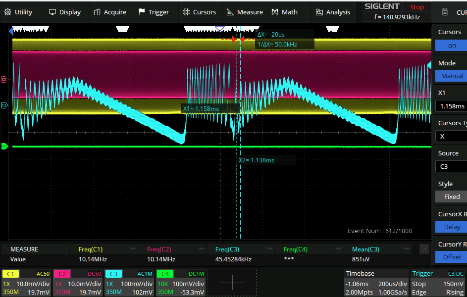
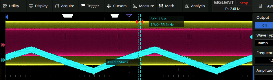
The PLL can lock on fine if the total deviation is below this:
VCO is not reversible
The reason for this seems to be that the bandwidth required of the VCO is not the same on the transmit and on the receive.
If we imagine that the PLL changes frequency in about 1ms and has a 1MHz/V transfer function then that means that in response to a 1V step input it will change the output frequency by a MHz.
The 1MHz error signal is then produced by the mixer and in order for the PLL on the receive side to lock on The PLL has to respond within 1/1MHz = 1us! So basically the VCO bandwidth has to be equal to max signal frequency * spreading factor.