Measuring frequency response
2k resistor on the output of the phase detecor and it’s associated frequency response. the 2k resistor more or less removed the phase shift from before
This is with no inverter, loop closed. Looks like the frequency response of the VCO isn’t really good enough here.
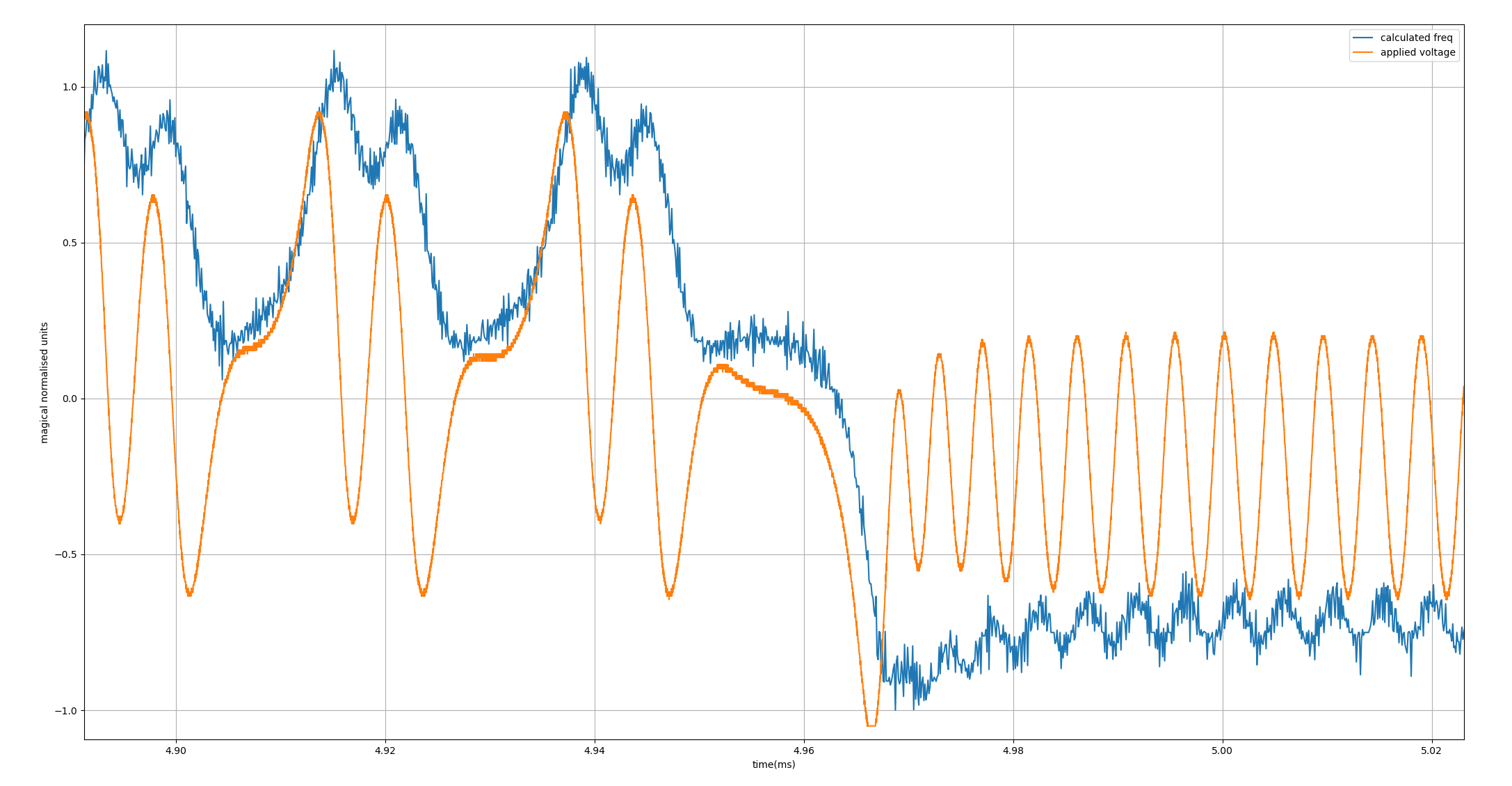
here is a scope trace of when the loop is closed with a switch. You can see that the applied volts initially goes crazy and the vco can’t keep up:

“Designing” a loop filter
I think maybe one of the problems is just not enough bandwidth in the loop. Perhaps you need way more gain and bandwidth than you think, like an op amp. Tried to do a brick wall filter at 1MHz using the online filter tool:
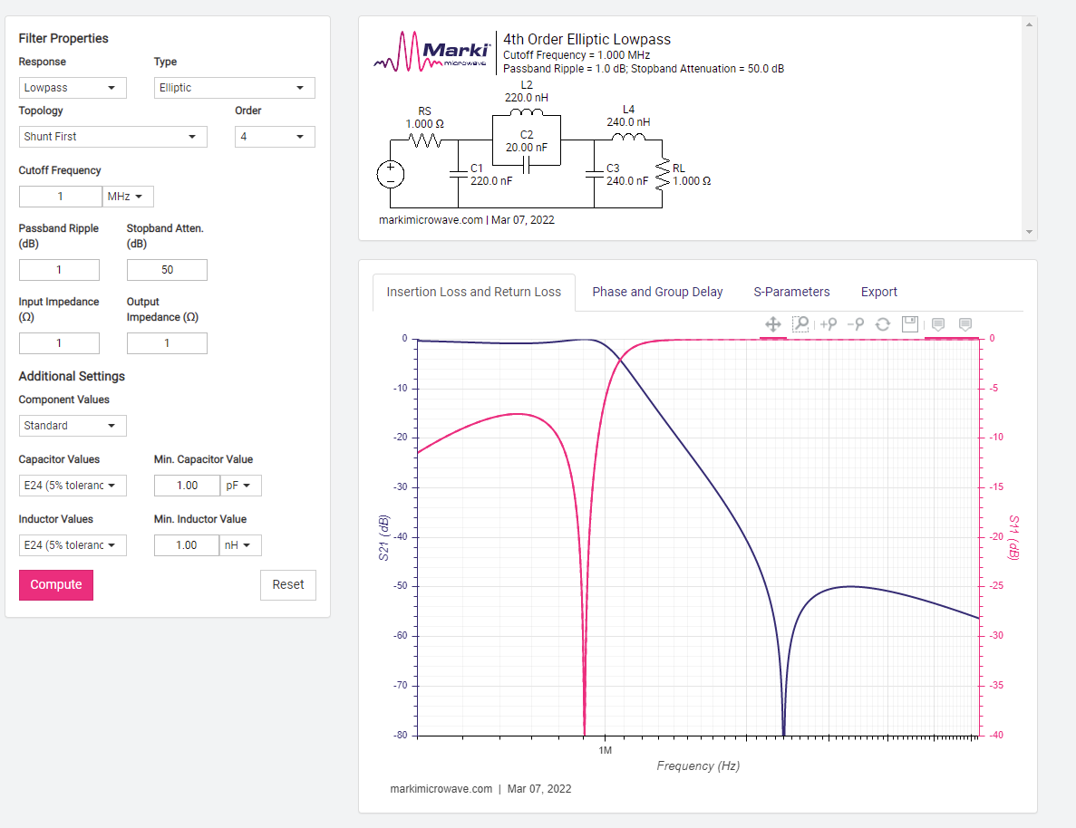
But to get reasonable inductance values I needed to set the impedance to 1R. This resulted in a 3dB bandwidth of like 20kHz when using a 50R output impedance on the AWG. Wonder why that is… Perhaps using the large discrete inductors is warranted.
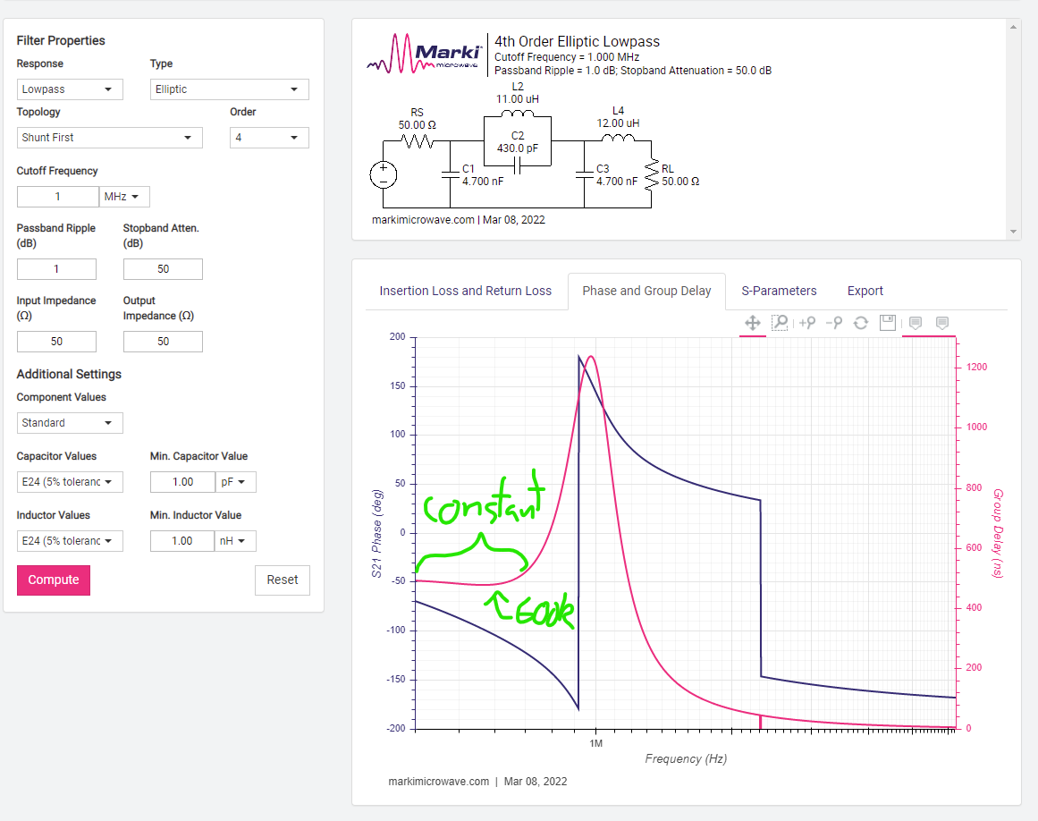
Adjusting for a 50R input and output impedance results in some still-plausible inductance values:
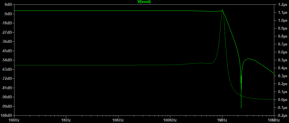
An LT spice simulation with actual component values seemed to think that things would also be OK:
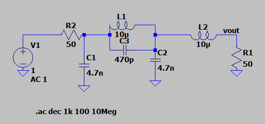
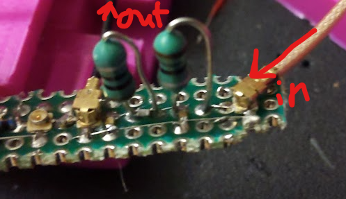
Draft1.asc …and the oscilloscope seems to agree! I think this is the best plausible loop filter I can make right now, and I would hope is good enough. Pic of the filter:
Thoughts on loop filter required bandwidth:
Group delay aka latency aka the devil
Let’s say that the max difference in freq we want to deal with is 1MHz, and the output of the phase detector is 100mV. So the sin wave phase signal inverts itself every quarter wave, or 1/1Mhz * 1/4 = 250us. We want to be comfortably within that range (10%?) so let’s says that the group delay of the filter needs to be below 25us over the bandwidth we are interested in, otherwise the control voltage that’s supposed to be correcting the phase back to zero won’t arrive in time and the phase will have inverted by then:
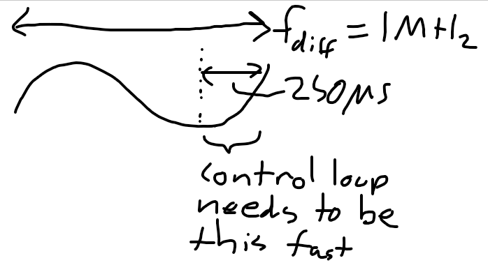
According to LT spice the 4th order elliptical filter has a flat 0.4us group delay all the way out to 500KHz. #TODO: measure the group delay of the circuit.
Bandwidth
This one is easy. We should just have a 3dB bandwidth that’s high enough. According to LT spice this one is good out to like a MHz but a quick scope measurement with the AWG seems to say that 500KHz is closer to the mark. This should still be good enough.
I think we might need more gain though. If you think about it if the maximum control voltage needs to be applied in order to correct the phase, then a phase shift of 180deg needs to be applied to correct the phase, since the correction comes from the error itself. Put like that, a pissant 100mV output from the IF aint gonna cut it. We’re gonna need a proper amplifier!
AC coupling
The LO and the RF signal are not going to be perfectly matched in frequency. So some constant DC offset is going to have to be provide to the VCO to make it match frequencies. That means all of the loop filters etc etc need to be dc coupled which they haven’t been so far (silly me). The art of electronics suggests using a differential amplifier as a DC coupled alternative to the common-emmitter amplifier.
Gain
I should measure how many MHz/V the VCO is and then calculate the required gain of the amplifier so that only a phase error of say 1/100 of a wavelength is required in order to generate enough voltage to correct the signal. So if the VCO is 1MHz/v (not too far off) and the IF output is 100mV, and then we want the full scale output voltage of the phase detector to be pretty big, prolly like 10V.