XOR gate as phase detector
Maybe the problem is with the mixer, not any phase response stuff in the loop filter. I have wired up the SN74AHC1G86 as a phase detector. Initially I was worried about getting enough swing on the output of the VCO’s to properly hit the logic levels but this turn out not to be strictly necesary, if you AC couple things into a vcc/2 voltage divider on the inputs then a few hundred mV is enough. I did need to turn down the power rail to 5V from 7V for compatibility, but I was gonna do that anyway. Here is what it look like with one input being a VCO output and the other coming from the AWG on the scope:
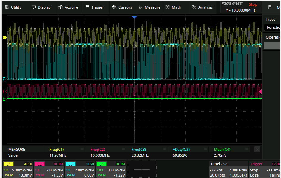
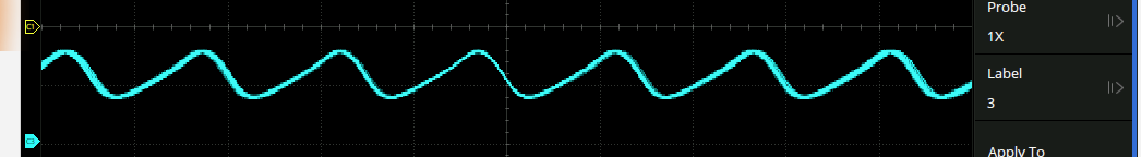
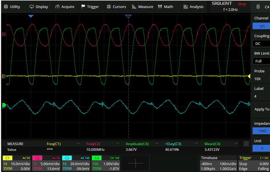
CH1: output of VCO CH2: output of AWG CH3: output of XOR Looks great! The interference from the rising/falling edgess on CH1 seems to be mostly probing related (it’s on a 100:1+ divider so as to not interfere with the actual circuit too much) Now to lowpass it. I hope that there aren’t too many problems here as the nominal ‘zero phase’ is at vcc/2. Taking the loop filter from here: Designing a loop filter once again and making sure to terminate the output of the filter at 50R, we get this:
Noice. Only problem is the measurement of the two input frequencies is super corrupted from the xor edges. I probed the actual inputs though and again this seems to be a probing artefact.
Bad tuning range
Perhaps as a result of reducing the supply voltage to 5V I notice that one of the VCO’s does not want to tune above about 10.5MHz without the amplitude dropping off a whole bunch. Perhaps adding more to C2 to increase the amount of feedback?
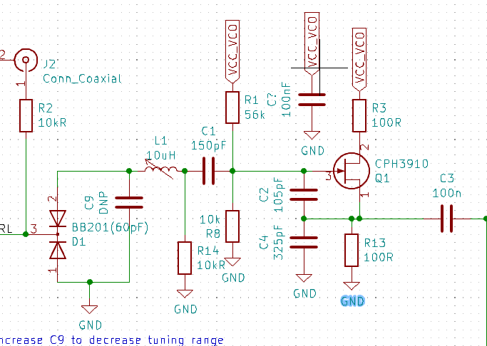
…Adding 100pF to C2 stops the oscillation entirely.
scratchpad: R13 to 300R. increased DC point, did not increase modulation amplitude C4 to 100pF. This increased the modulation to 1.5V I notice that probing the output increases the modulation amplitude slightly. Perhaps that means that I’ve gone too far, and C4 should be increased a bit? It did not. 1.4→1.13vpp. C4 back to 100pF, increasing C2 by 47pF stops modulation entirely. Note: impedance of 100pF is 159R at 10MHz. that actually sounds a bit low, so maybe a very small C4 is what’s required. CHange C4 to 20 or 50 pF results in no oscillation.
Fiddling with locking
Perhaps one of the reasons that the thing doesn’t lock is that the control output is in the wrong wrange (maybe it’s 3-4v output but 2v is needed). Changing R35
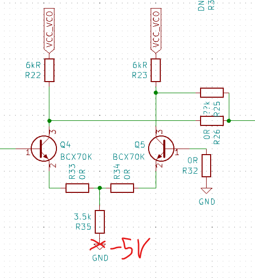
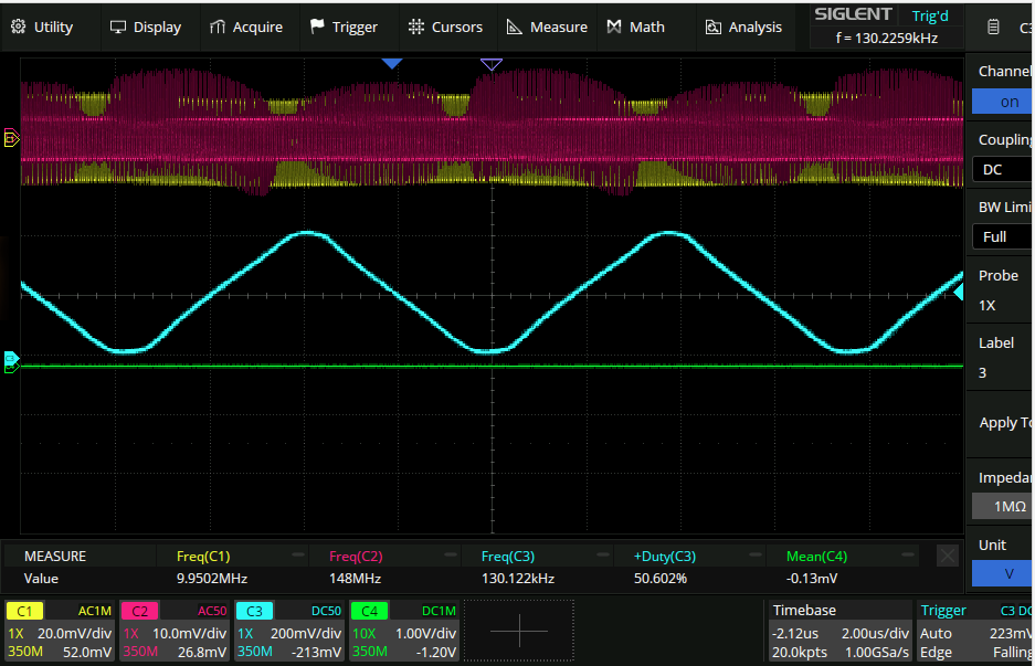
to a potentiometer allows the DC point of the output to be adjusted. Swinging over the full range does not result in a lock, but it does result in two interestingly distinct phase oscillations:
and

as a result of wiggling the output up and down. To me this kind of looks like the feedback is the wrong way round and the two modes above are the input signal being above and below the VCO. Taking the opposite sign outputut from the diff amp (R26 instead of R25) we get:
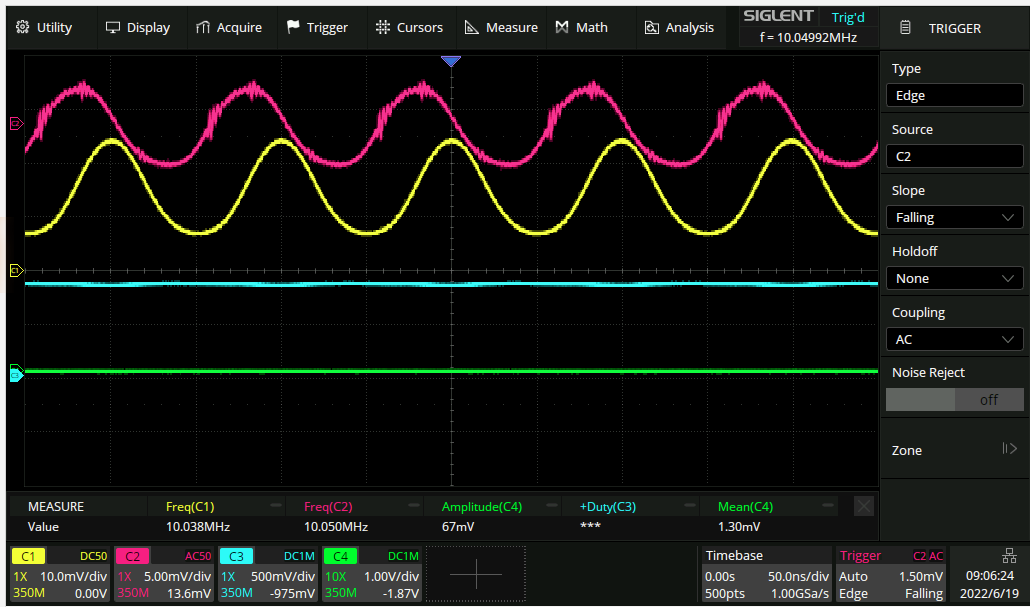
…A locked PLL! ta-dah! I had assumed previously that it did not matter if positive or negative feedback was taken from the output of the diff amp, as that would jusst change whether the loop locked on the rising or falling edge of the phase detector output. This isn’t a conclusive investigation but it seems I was wrong about that. The lock ranges from the state:
- 900mV, 10.05MHz(ish)
When the pot that gives the VCO a sensible voltage while the loop is disconnected is itself disconnected, the PLL fails to lock at any frequency and looks like this:
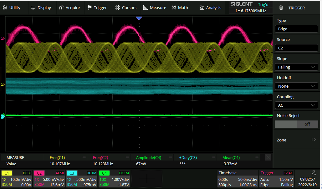
The persistence view of the scope suggests there is some locking adjacent behaviour going on here.
Better isolation
Overall though even though the lock is quite stable itcan still be disrupted with the aerial screwdriver technique. I had removed the buffers on the output o f the oscillators so maybe putting those back in will help. The BCX70K doesn’t really have any appreciable gain at 10MHz apparently, so I have switched to the BFR106 which according to LT spice will do just fine. The following circuit also does quite well in practice:
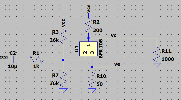
(green is the output.)
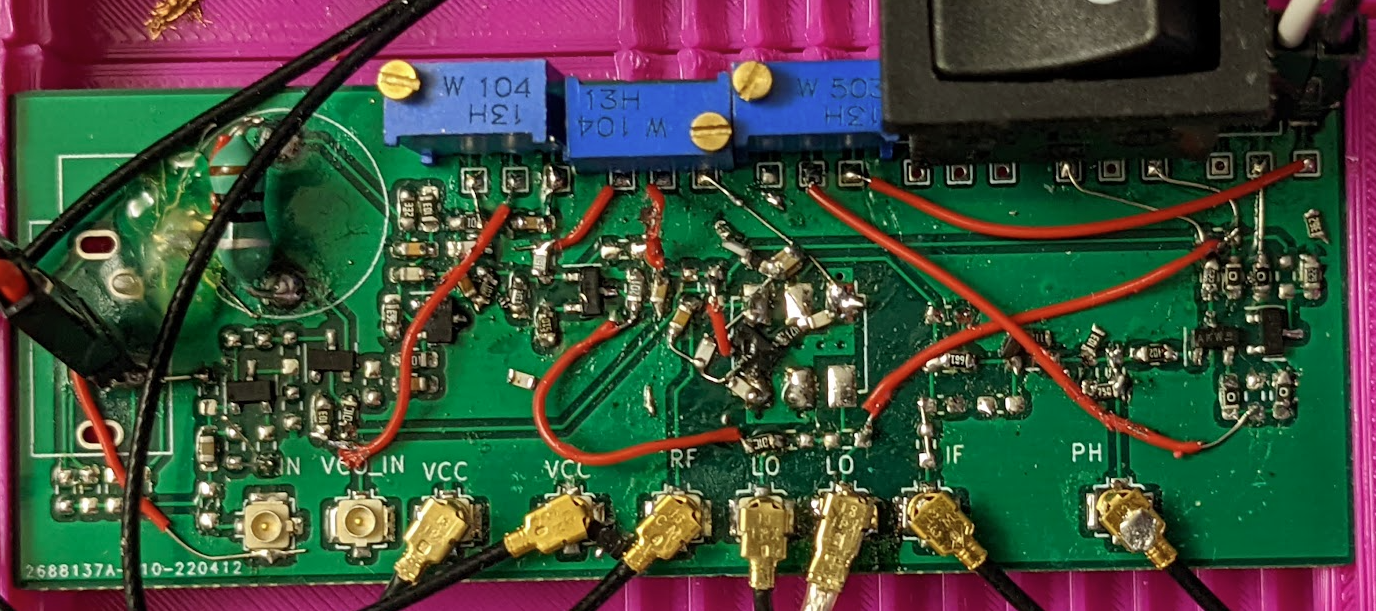
I did this on both oscillators and although there are now nice large distorted square waves going into the XOR gate, the circuit still has the same screwdriver susceptibility. You can even turn the lock on and off with the right gesture. The circuit also has quite a bit of screwdriver velocity sensitivity also. Current state of the circuit btw:
Where’s that field?
Being quite a lot longer than the circuit itself, the screwdriver is a rather nonspecific way of finding the location of this external interference susceptibility. A small magnet does quite a lot better. Couple of observations:
- The circuit seems to be most sensitive around the actual VCO. When the magnet is moved over that bit (irrespective of the magnets orientation) then the PLL losess the lock.
- the big inductor changes its inductance a lot in the presence of the magnetic field! the frequency goes from 10→14MHz!
- Hot gluing a ~2mm chip of neodymium magnet on the end of a platic spatula reveals that it is definitely the inductor and only the inductor that is susceptible to external interference. The two circuits have two different sized 10uH inductors on them and the smaller one is much more susceptible. Perhaps this is why shielded inductors are a thing…