Following the revelation previously that the reason that the circuit was sensitive to screwdrivers was the unshielded inductor we need to switch to some unshielded inductors. I have purchased some but they don’t work. Time to find out why with the nanoVNA.
Inductance measurement principle.
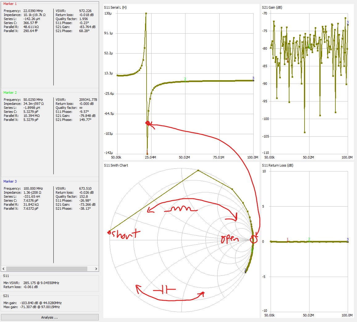
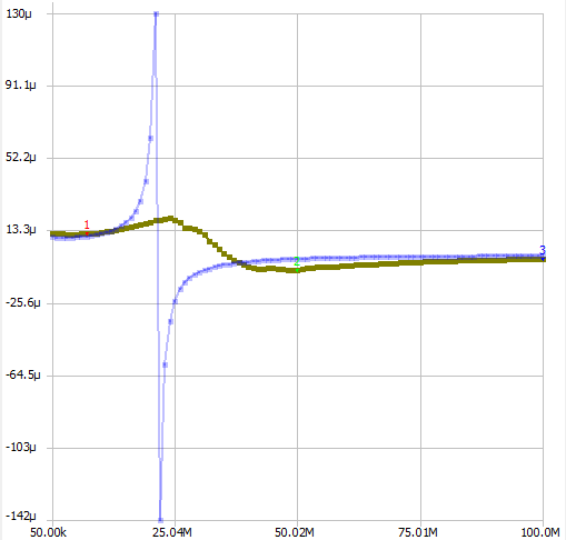
Who knows how smith charts work? Not me, but let’s proceed anyway. It’s known that real world inductors turn into capacitors at some point which is the point where the inductor crosses the ‘x’ axis on the smith chart. It’ss probably highly nonideal before it gets there, though.
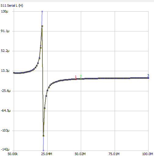
Big wirewound OG unshielded inductor:
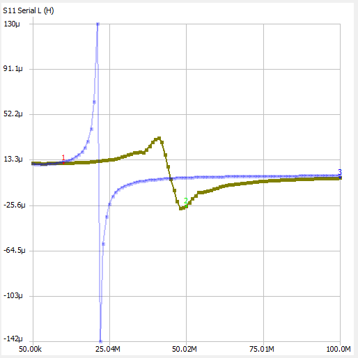
NRH2410T100N (Big SMD):
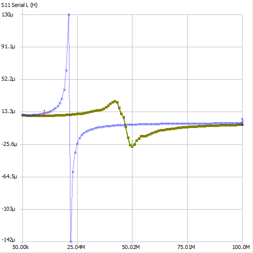
SWPA3012100MT (Small SMD):
AIML-0603-100K-T (0603 SMD):
Those were the wrong graphs.
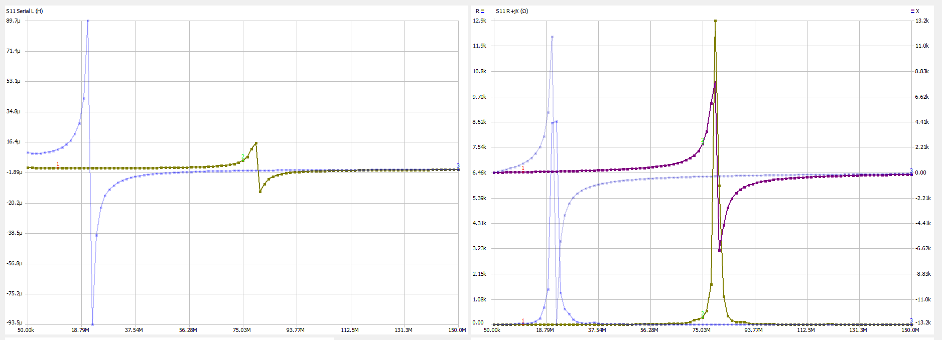
According to here I should have been using the R+JX graph to measure the inductor Q, since inductor Q is defined as X / R.
Here again is the AIML-0603-100K-T:
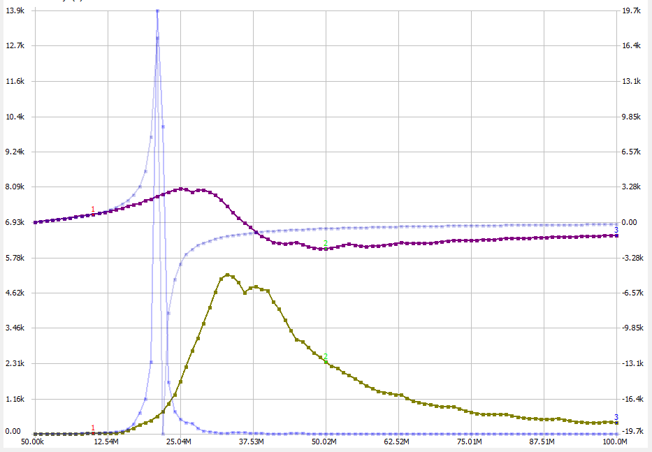
At 10MHz it is 19+j743R. ⇒ 39Q The big inductor at that 10MHz is 36.9+j758R ⇒21Q. There’s clearly a much higher spiky bit for the big inductor. I’m not sure why a
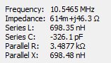
Attach a magnet to the big inductor:
As mentioned before Where’s that field This changes the frequency of the VCO from 10 to 14 MHz. The parameters of the magnetised inductor are:
Actually everything is fine.
It turns out that the AIML-0603-100K-T and the NRH2410T100N actually work fine - the circuit oscillates with both. with about 600mV on the varactor diode they ocsillate at 10 and 12 MHz respectively. That’s a bit high, it would be nice if they oscillated starting with a decent amount of control voltage on the varactor diode. The second copy of the circuit does not oscillate though. Once again we have a mismatch… Time to go through and find the differences… …I ended up needing to change the bottom feedback capactor C4 to 100pF and the emitter resistor R16 to 330R.
After all that though the circuit is only slightly less susceptible to perturbations with a screwdriver. The PLL won’t actually lose its lock.
We have a lock (again)!
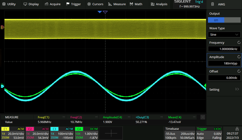
This time you can play music through it. Beethoven comes through crystal clear, although there is a bunch of EMI if the music is played from a PC rather than an isolated source like a phone. The maximum modulation depth on the input that can be tolerated is about 180mV:
But any more than that and it starts to lose its lock:
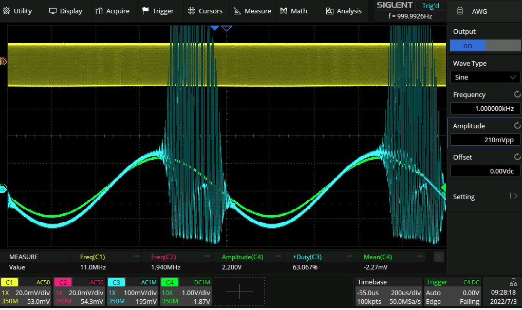
Not quite sure what the cause of that is. This is a fairly narrow range though.
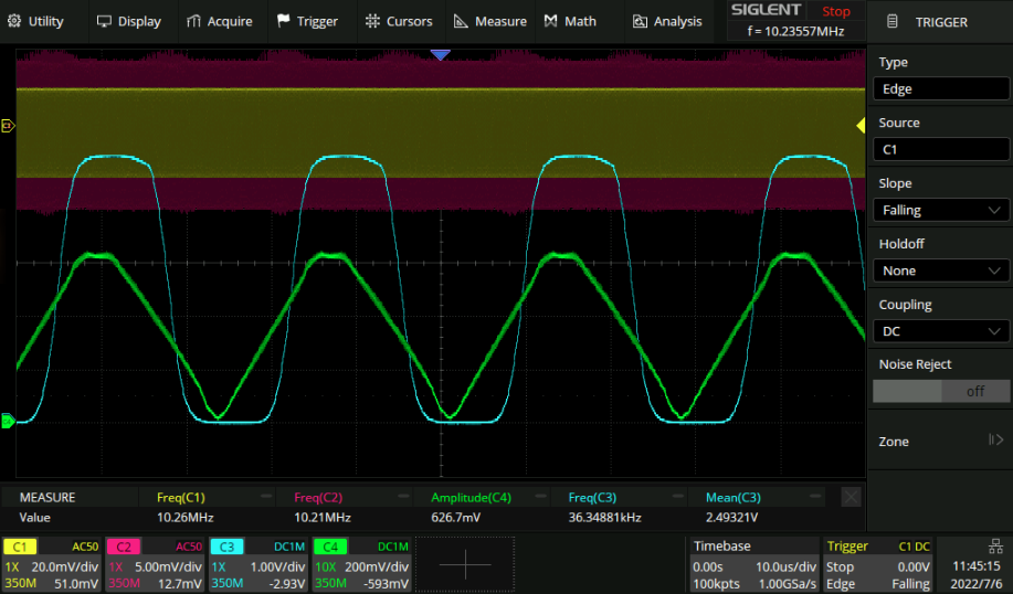
Taking a zoomed in look at the PLL with the maximum amplitude lockable sine wave:
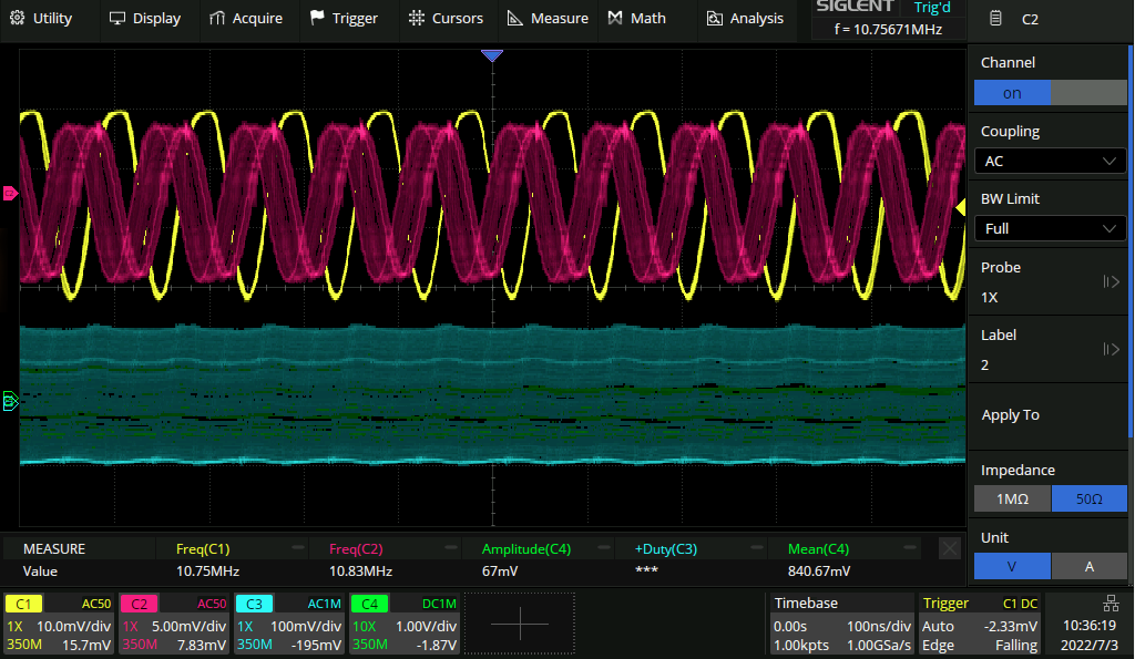
We can see that there is a great deal of phase shift between the two outputs. I think that means that we need a lot more (10x?) open loop gain in the loop filter so a smaller error is needed to get our control voltage. Back to the Bode plots!
Loop filter gain (again)
Currently the loop filter is sitting at a rather comfortable 30dB of gain as before:
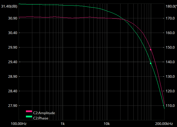
I would have thought that this would be plenty to get a lock over quite a wide range of voltages - perhaps there is something more going on here, like the lowpassed phase signal being unreasonably small.
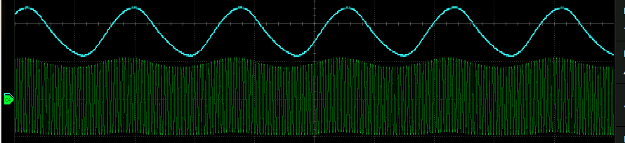
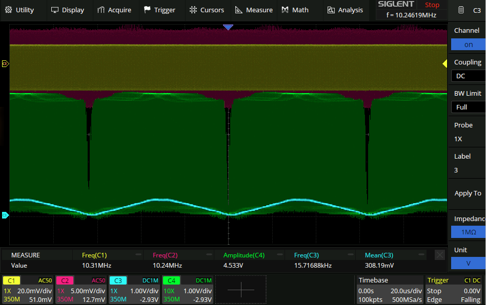
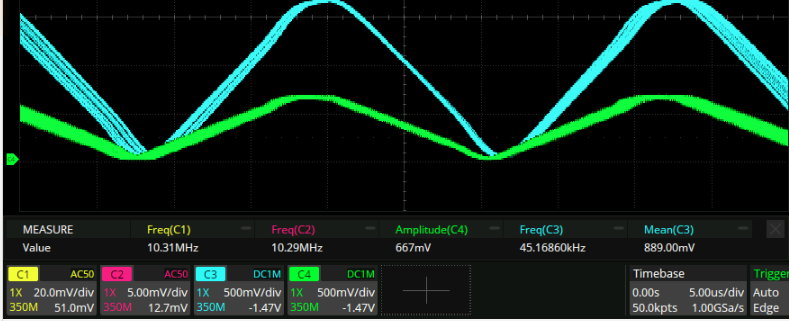
Disconnecting the feedback from the PLL the phase looks like this in open loop mode with a small difference in frequencies:
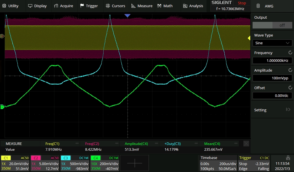
Where green is the lowpassed input to the diff amp and blue is the output. It looks like the gain is quite low for the positive sections of the green waveform, but quite high for the negative sections. The DC level of the diff amp can be adjusted with a potentiometer in place of R35. Interestingly if you adjust it low enough there is a bit of “reflection” at the bottom of the waveform where the gain goes positive again:

Probably best to avoid that…
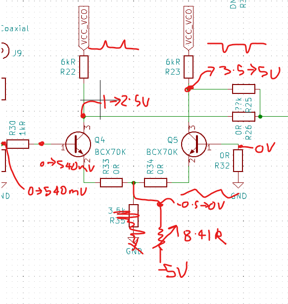
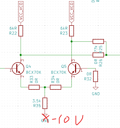
Remembering that this is a differential amplifier, the correct thing to do for adjusting the DC input level is not to adjust where the negative rail is, but to adjust the voltage of the base of the other transistor (Q5):
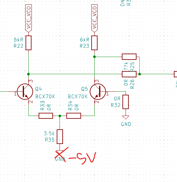
Putting a potentiometer between VCC and -5V is the obvious way to do this. From LT spice only a very small DC offset creates a very large effect thoough.
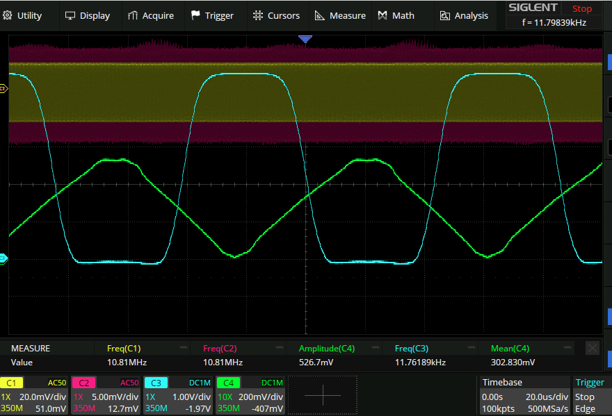
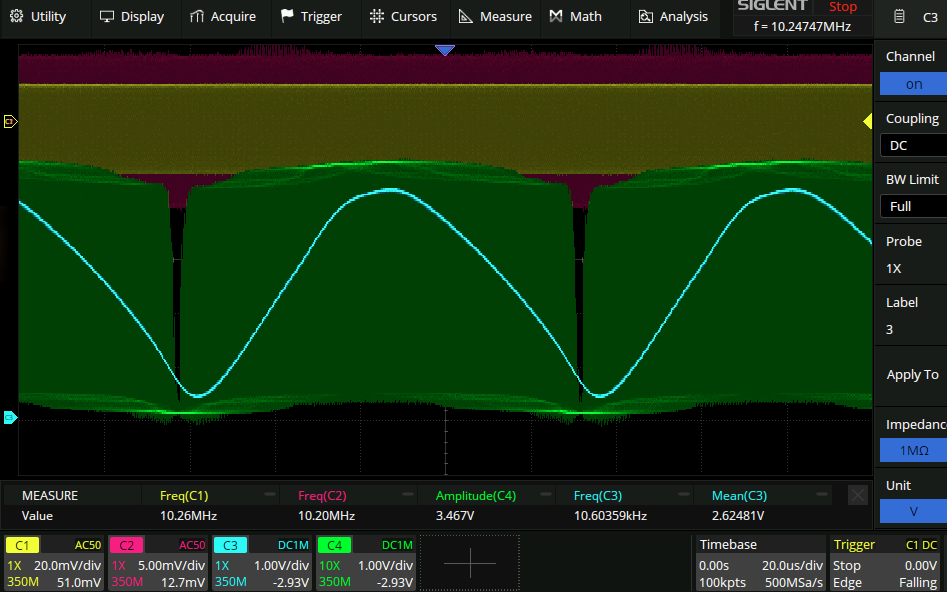
Vunderbar! Adjusting the base of Q5 to be ~250mV (half of CH4) results in this lovely symmetric square wave. no wonder the PLL had trouble locking before…
Proper things don’t work.
…And now the PLL won’t lock. It exhibits that “popping” behavious described before where you can adjust the frequency of the input signal to match that of the VCO and then the VCO jumps to the other side of the input signal :(
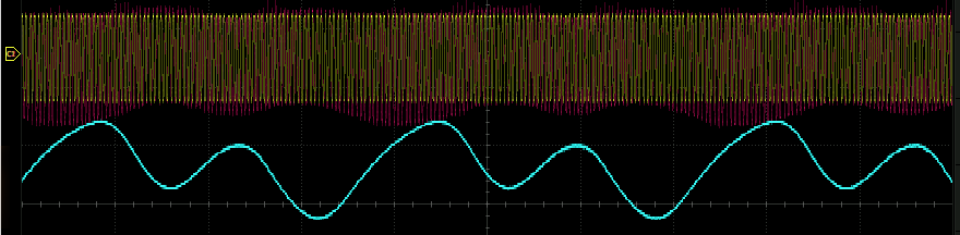
Looks like there’s some coupling between CH2 and the phase signal. Probing the output of the colpitts oscillator (before the buffer) look like this:
So there is some definite coupling. Not great. Perhaps this is just the frequency dependent amplitude of the VCO though. Remembering from before that the phase signal seemed to switch from positive to negative gain at some point I switched from the negative output of the diff amp back to the positive. This did not help. It is once again possible to get things to lock with the loop open though.
Let’s go back to when things worked and take more detailed measurements:
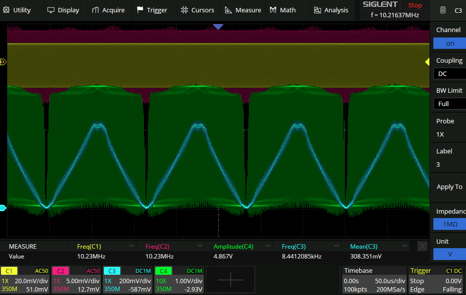
The above measurements were taken with the loop switch open. Switching back to the diff-amp-works-great-but-pll-doesn’t-lock state things look about the same for the various DC levels. Since the difference in voltage between the two bases seems to be critical here I put R35 back to a fixed 8k resistor and put a voltage divider pot on Q5 base to adjust the base voltage there. If the parameters [Input frequency, negative supply voltage, Q5 base voltage] are all precisely aligned then the loop locks no problem. Any deviation from that and it won’t. Here is the input vs output of the diff amp with the above working configuration but in open loop:
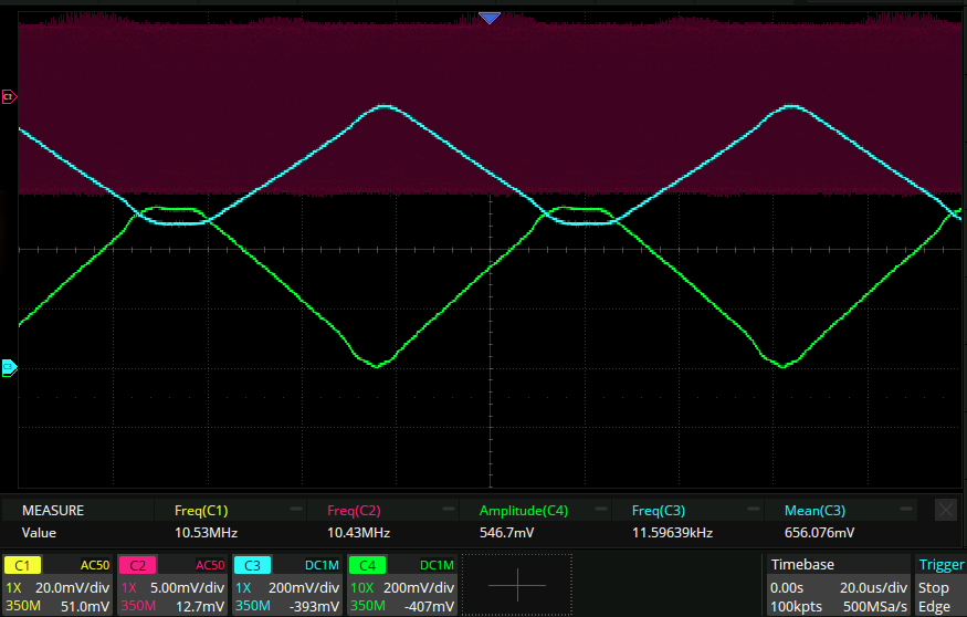
At this point the above parameters are [10.5MHz, -6V, -300mV]. Investigating each parameter in more detail:
- Q5Base:
- highly negative voltage like -3V is not a problem.
- From the locked state 170mV will unlock. The top part of this waveform has way higher gain as you would expect.
- From the unlocked state -41mV will lock (there is hysteresis). -41mV looks more or less like the triangle wave above. ^fccd30
- When adjusting Q5Base across the range of good voltages there is no phase shift between the two waves prior to unlocking, it is an abrupt transition. The Q5Base observation shows that the feedback loop just straight up doesn’t like a high gain feedback loop. In both the working and nonworking states the feedback is negative, it’s just that when Q5base voltage is adjusted to the average phase voltage to get proper gain on the positive and negative phase swing things just refuse to lock. I always though that when it came to feedback loops more open loop gain was always a good thing. This seems to be contradicting that.
Side note: harmonics??
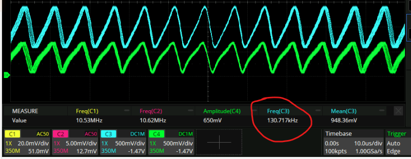
With exceedingly careful knob twiddling I got this to occur:
This shows the locking to one of several(8?) different phases. To me this is indicative of the feedback occuring at a higher frequency harmonic. If things locked at an 8x harmonic then the fundamental would appear at 8 different phases like this. The waves in this circuit are deliberately large amplitude and highly distorted so I suppose this is possible, although it’s also what loop filters and whatnot are supposed to prevent.
Loop filters (again^2)
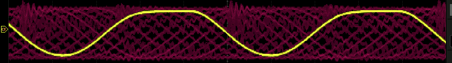
I think that I need a pot on both R35 and Q5base is needed. Fiddling around with the pots, voltages and frequencies for a while I was not able to gradient descent to a proper solution. So I took a look through the literature again and was reminded that everyone is like “yeah nah yeah nah a plain ol RC is all you need”. (Note: plain ol RC does not invert signal of course). So I took the lowpasssed output of the phase detector and put it straight back onto the varactor diode, bypasing the diff amp section entirely. The phase detector output is only 500mV in amplitude and so I had to adjust the input frequency to something that required a varactor diode voltage of <500mV but after doing that things locked fine and pretty robustly (could put in a 300mVpp modulation signal before losing the lock). Note however that this time the PLL locks on the rising edge of the VCO:
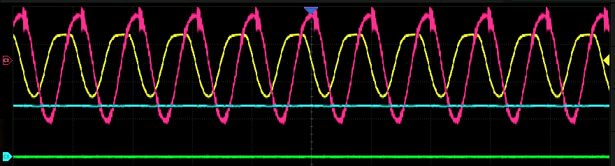
Yellow: Incoming signal, Magenta: VCO. It was different here. So in order to lock to the full vcc range I think either:
- Going back to the noninverting output of the diff amp to apply some hopefully non-phaseshifted gain to the passive filter
- Or bearing in mind the XOR phase detector should theoretically be able to go all the way from 0→VCC just redesigning the passive filter to have less of a voltage drop. The latter seems more efficient as the reason that I put in the diff amp in the first place was back when the mixer phase detector was being used. Option 2 filter looks like this:
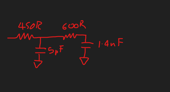
…But I can’t seem to get the PLL to lock at that frequency. Same popping behaviour as before. Time to take a bode diagram of this filter to compare it to the [other one.](^34b78a) New RC filter:
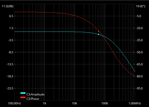
Old filter measured again with realistic load on the output of the filter (75R):
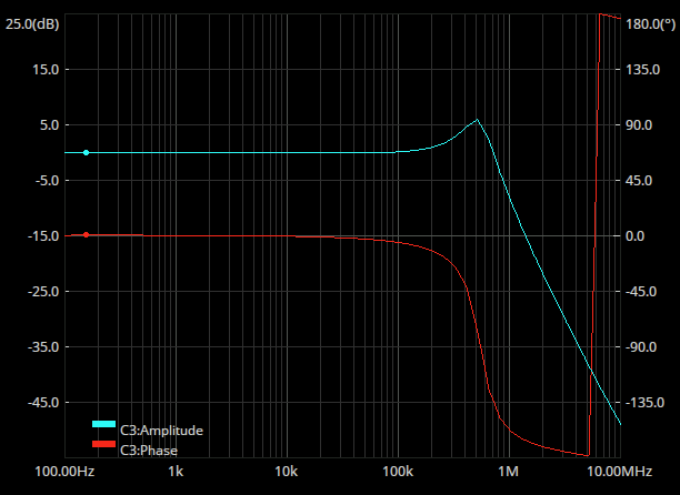
Well the LC filter is certainly more dramatic but I don’t exactly see why it works and the other doesn’t.
From the above observation about being able to lock on the rising or falling edge of the VCO, I gather that I have achieved a lock on both the rising and falling edges of the XOR phase response. So presumably what is left over is to divine what’s wrong with the above loop filter. I think that the response time of the VCO itself is probably about [60Khz](^eed27d).
At that frequency both of the filters aren’t doing much, altough the plain RC one has a 30deg phase shift. Maybe that’s it?
Also it’s not in the bode diagram for some reason but the p2p amplitude of the RC filter is a fair bit higher (1-4Vish) than the LC one (180-420mVish).
I also discovered that a lock can be achieved if the RC filter and LC filter is connected, with the output of the RC filter going to the varactor diode and the LC filter just acting as a load. So presumably either a phase shift or an amplitude shift needs to be induced, and this is a starting point to find out which.
Here is the output of the phase detector when unlocked and with both the RC and LC filters attached. Green is raw XOR output and Blue is filter output.
Here just the RC output:
Next step is to load down the RC filter until it has the same amplitude as the LC version. Here is the output of the RC filter with 70R loading it down (exactly the same resistance as the loading on the output of the LC filter incidentally).
(Note the vertical scale for CH3 in this picture).
This filter results in a PLL that can track 410mV worth of frequency swing which is more than before.
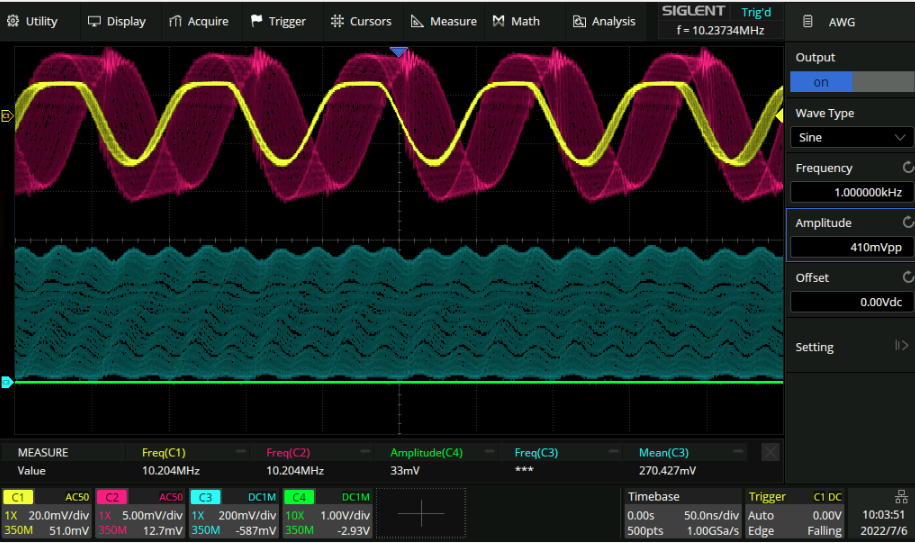
The intention of this experiment wass to plain ol divide down the voltage, not change the impedance as actually happened. This could be done with a high input impedance buffer followed by a voltage divider. I don’t have such a thing on hand though so that particular experiment shall be put on the shelf for later. Instead we can add a bunch of gain to this waveform and see if the PLL can still lock with it. Here we are:
Lots of gain but apparently a fair bit of phase shift, too. I think the next step will be to reduce the gain to something like 2x and see if that still works.
Gain reduction
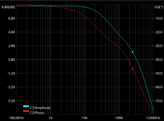
Changing R33 and R34 modifies the gain to about 2x:
However the PLL does not seem to lock in this configuration either. It doesn’t seem to have much bandwidth:
And when the bandwidth drops off the output tends to the DC output level which is of course at the wrong voltage. LT spice seems to think the amp should have a bandwidth of like 1MHz and previous experience agrees so I’m not sure what’s going on.
A lock(barely):
I did get the PLL to lock with the diff amp (barely). Adjusting the DC output, the lock frequency, or the Q5base voltage by even the merest of whiffs loses the lock and then a great deal of fiddling is required to get it back. You can’t just throw the lock/unlock switch back and forth and have it lock repeatedly. Here is the amplifier performance:
Utter trash. No wonder it locks over such a narrow range. Recalling that the original purpose of this was to find out whether having even a perfect amplifier was a bad thing I think switching to an op amp amplifier just to eliminate variables would be a good thing.