Main goal
This fm radio project has dragged on long enough. If I could build one of those antennas with inductors at the bottom that work at low frequencies then I could avoid the planned upconverting step to 915MHz and just operate the system directly at 10MHz. Not particularly FCC compliant, but for desk→headphone transmission the power should be low enough that it’s OK.
Initial tests
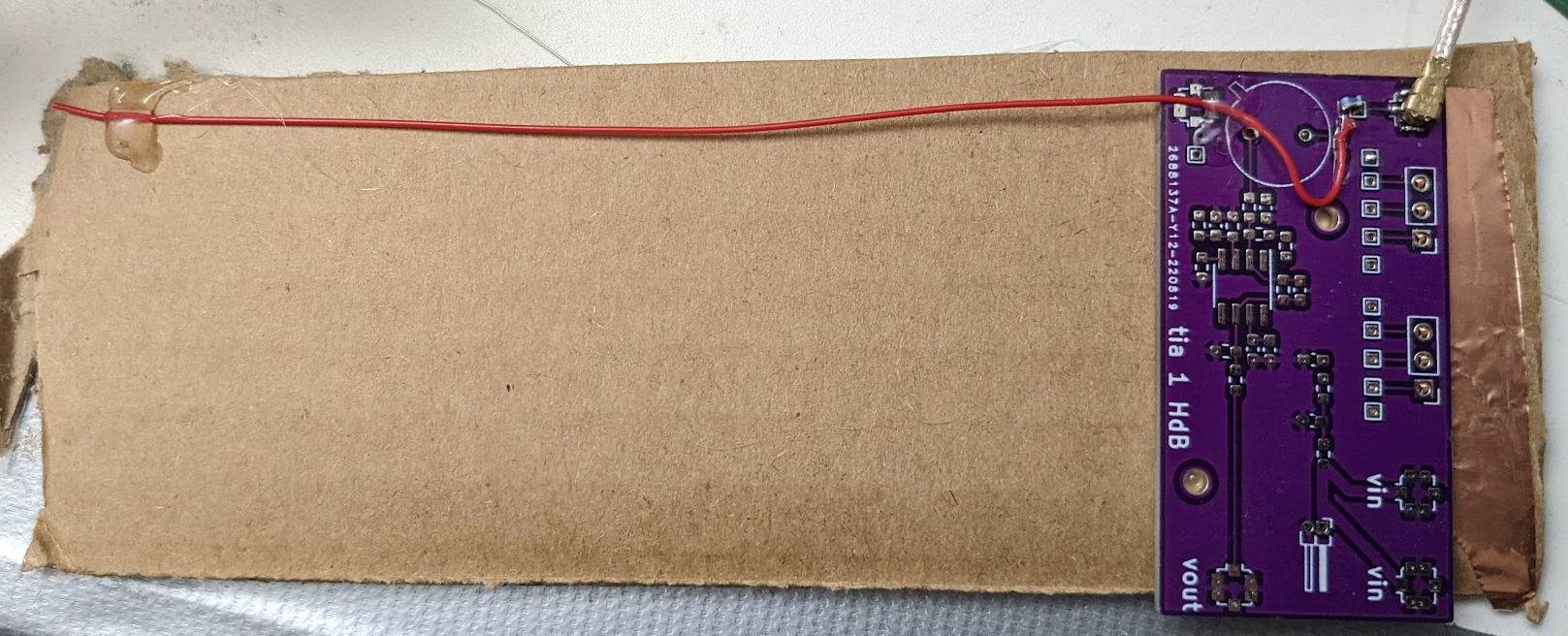
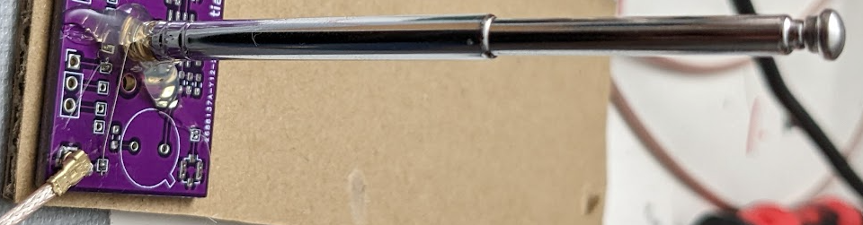
I stuck a piece of wire to a pcb like so:
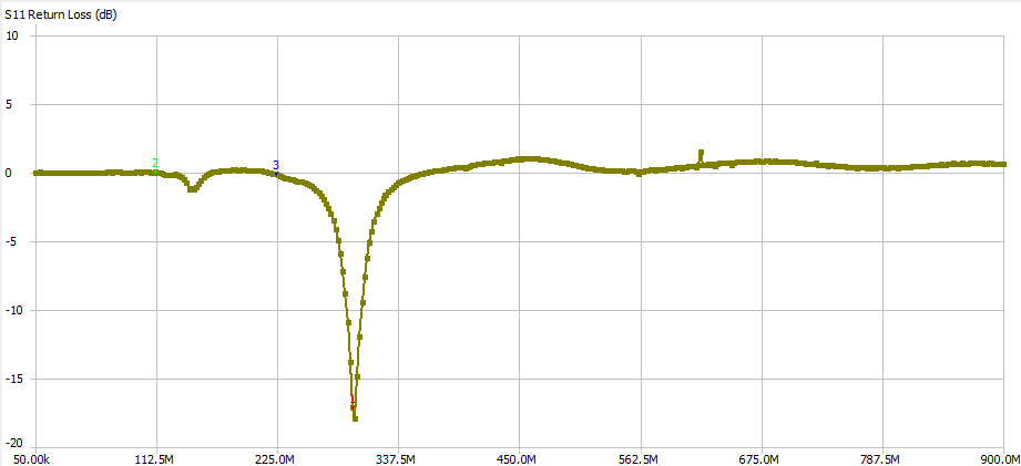
 The S11 return loss looks like this:
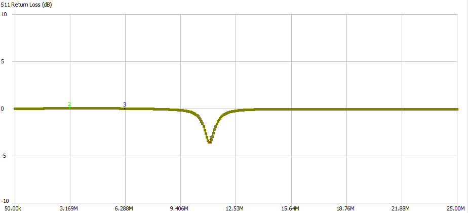
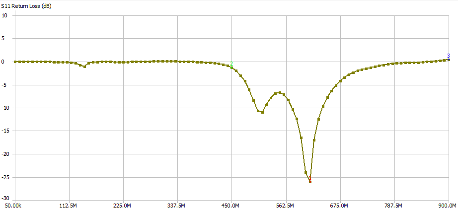 with a minimum at 612MHz, which sounds about right. -25dB means that 95% of the energy gets transmitted I think.
Adding a 10nH inductor to the base makes it look like this (I changed the settings):
with a minimum at 612MHz, which sounds about right. -25dB means that 95% of the energy gets transmitted I think.
Adding a 10nH inductor to the base makes it look like this (I changed the settings):
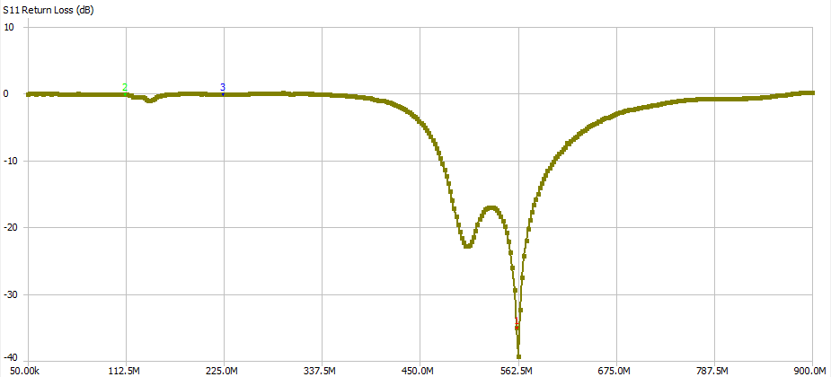 it dropped the frequency a bit, but not by that much!
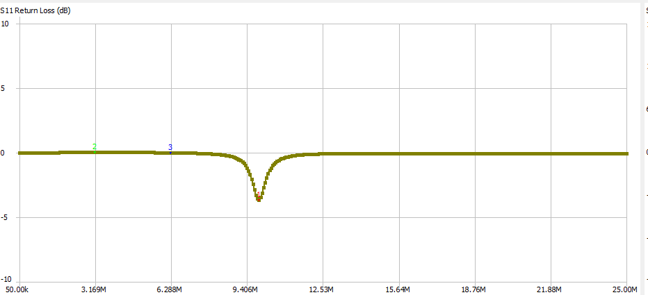
Time to 10x the inductor. 100nH looks like this:
it dropped the frequency a bit, but not by that much!
Time to 10x the inductor. 100nH looks like this:
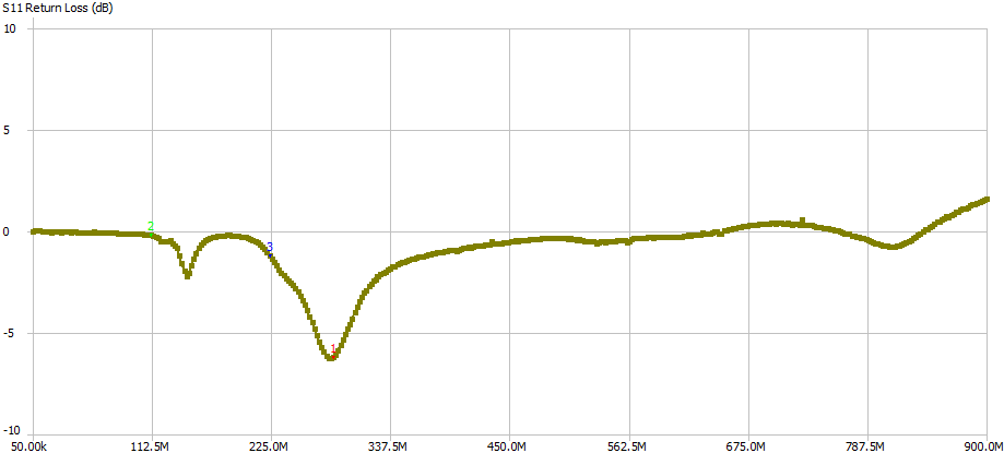 still not even close to being low frequency enough, and the transmission has dropped to like 6dB / 50% of the energy.
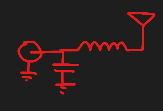
I’ve heard that there’s this thing called “impedance matching” that you are supposed to do too, so I added a 5pF cap to ground like so:
still not even close to being low frequency enough, and the transmission has dropped to like 6dB / 50% of the energy.
I’ve heard that there’s this thing called “impedance matching” that you are supposed to do too, so I added a 5pF cap to ground like so:
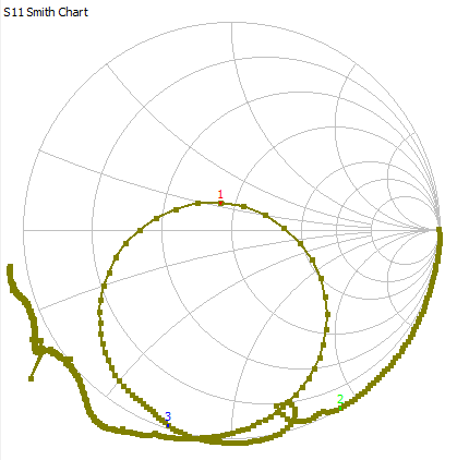
 Which results in this:
 Pretty nice!
Cut-and-try seems like a bad policy here, even if the state space is really small. You are supposed to like balance the the capacitance with the reactance, or something. Now for the question of how much “capacitance” equals how much “reactance”.
Surely this can be measured with a VNA!
Pretty nice!
Cut-and-try seems like a bad policy here, even if the state space is really small. You are supposed to like balance the the capacitance with the reactance, or something. Now for the question of how much “capacitance” equals how much “reactance”.
Surely this can be measured with a VNA!
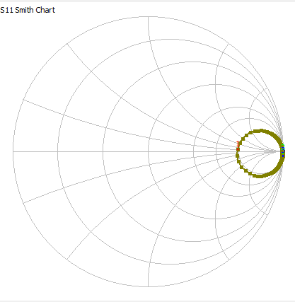
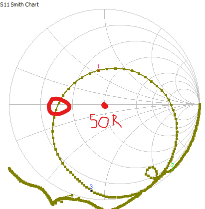 I believe on the smith chart where the trace crosses the horizontal axis is where the impedance is purely real (what we want, I think). This is actually pretty close already to the best S11 loss (denoted by the red 1). Deviations along the horizontal axis are away from 50R but I don’t think we care about that so much since we are making our own amplifier anyway.
Time for our first hypothesis: since the red 1 is in the inductive half, we want to add some more capacitance to bring it towards the capacitive half!
I believe on the smith chart where the trace crosses the horizontal axis is where the impedance is purely real (what we want, I think). This is actually pretty close already to the best S11 loss (denoted by the red 1). Deviations along the horizontal axis are away from 50R but I don’t think we care about that so much since we are making our own amplifier anyway.
Time for our first hypothesis: since the red 1 is in the inductive half, we want to add some more capacitance to bring it towards the capacitive half!
 I am a tuning genius.
Measuring real antenna impedance
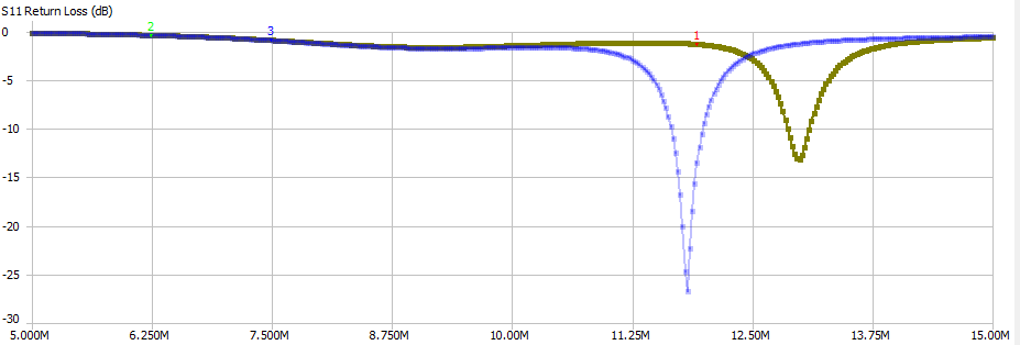
To calculate the matching network I think we need to measure the antenna impedance at our target frequency. This will be approximately infinity ohms I think.
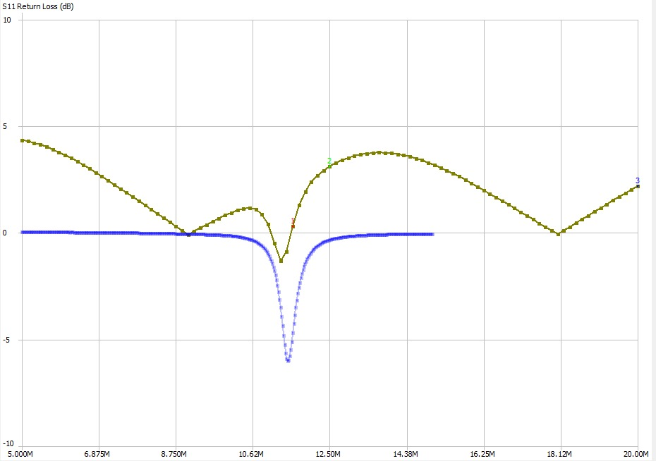
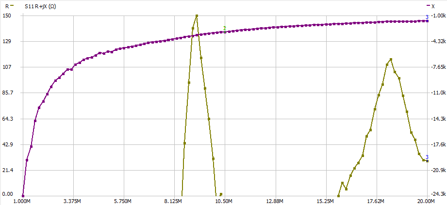 This is the R+Jx impedance plot from 1-20MHz. at 10Mhz it’s basically NaN - 3.2kR. Does that mean that I need an inductor that’s Z=3.2kR at 10MHz? without bothering to actually look the answer up I’m going to go ahead an say yes!
So according to that means my inductor should be 3200/(2pi10e6) = 50uH. That sounds… reasonable?
And then I think I’ll need to add a capacitor in order to match the impedances to the output of my amplifier. Maybe.
This is the R+Jx impedance plot from 1-20MHz. at 10Mhz it’s basically NaN - 3.2kR. Does that mean that I need an inductor that’s Z=3.2kR at 10MHz? without bothering to actually look the answer up I’m going to go ahead an say yes!
So according to that means my inductor should be 3200/(2pi10e6) = 50uH. That sounds… reasonable?
And then I think I’ll need to add a capacitor in order to match the impedances to the output of my amplifier. Maybe.
Scrounging about for inductors (again):
Here is a promising inductor 100uH that I could have had two of in parallel:
 SRF is 7MHz though :(
Stacking 5 of a Previous resistor (AIML-0603-100K-T0 in series gives this:
SRF is 7MHz though :(
Stacking 5 of a Previous resistor (AIML-0603-100K-T0 in series gives this:
 Honestly I don’t see why people call antenna design hard, this is all going according to plan. Suspiciously so, in fact.
Since our antenna is basically an open circuit, I think adding a 2.3kR capacitor might be what is required. That’s a 1/(2*pi*2.3e3*10e6) = 7pF capacitor. Since we are adding all these whopping great inductors in I kinda expected something bigger, but OK.
Honestly I don’t see why people call antenna design hard, this is all going according to plan. Suspiciously so, in fact.
Since our antenna is basically an open circuit, I think adding a 2.3kR capacitor might be what is required. That’s a 1/(2*pi*2.3e3*10e6) = 7pF capacitor. Since we are adding all these whopping great inductors in I kinda expected something bigger, but OK.
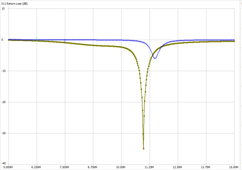
 welp that just moved the resonant frequency down to 9.8MHz and did nothing to the S11. Not that surprising really.
As a sanity check I removed the actual antenna to make sure that it was having an effect. Here is an A/B:
welp that just moved the resonant frequency down to 9.8MHz and did nothing to the S11. Not that surprising really.
As a sanity check I removed the actual antenna to make sure that it was having an effect. Here is an A/B:
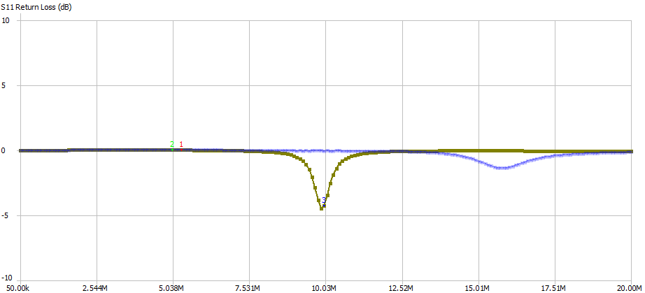 Seems like it is the inductor!
Transmission between antennas
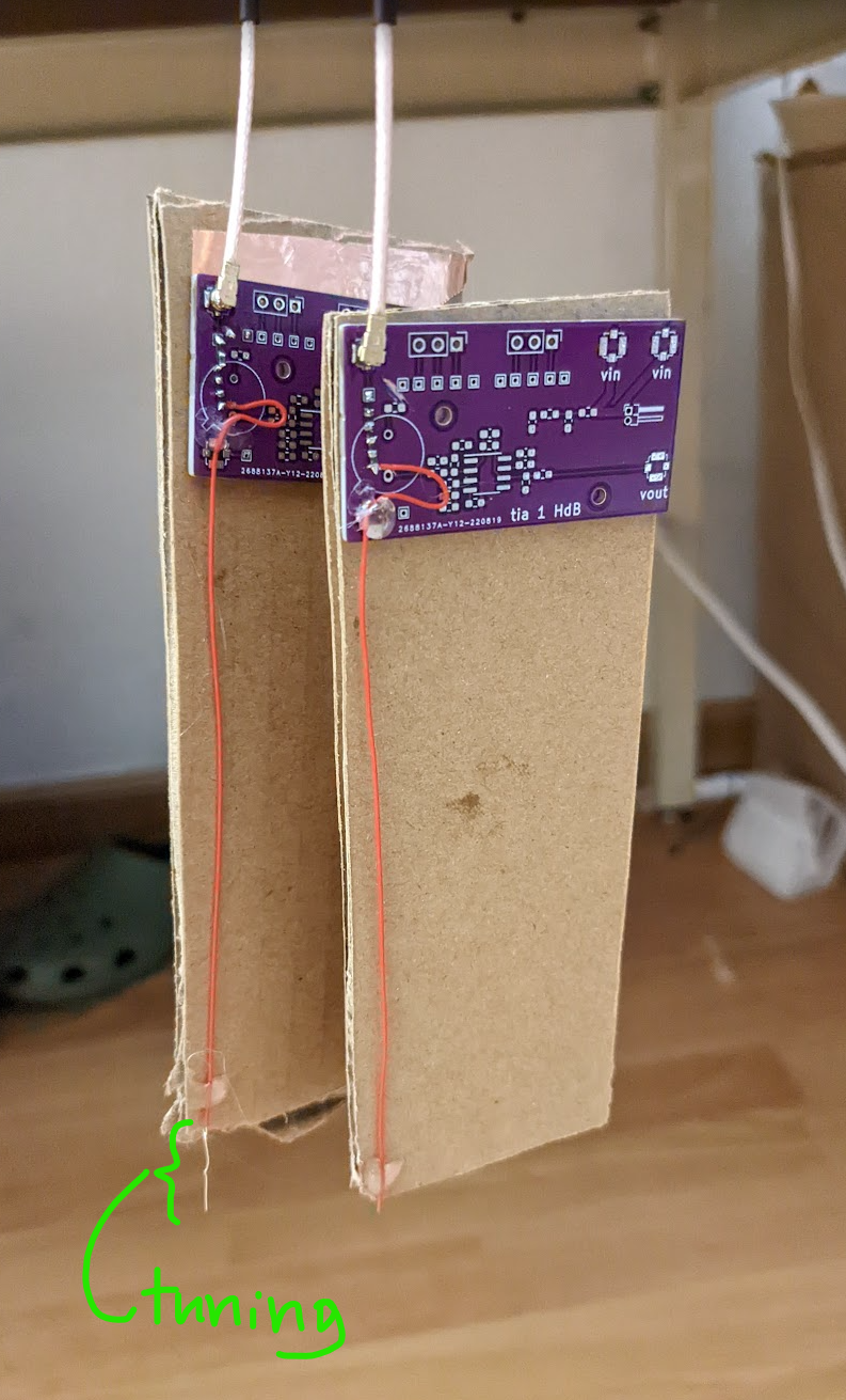
To really check if the antennas are doing something and I don’t just have some loss at a certain frequency I think the best thing to do is make two of the same antennas and transmit between them. here is an initial attempt:
 …Not great, but not too hard to adjust I would think.
Turns out just having the antenna on vs off the desk can make this much difference:
…Not great, but not too hard to adjust I would think.
Turns out just having the antenna on vs off the desk can make this much difference:
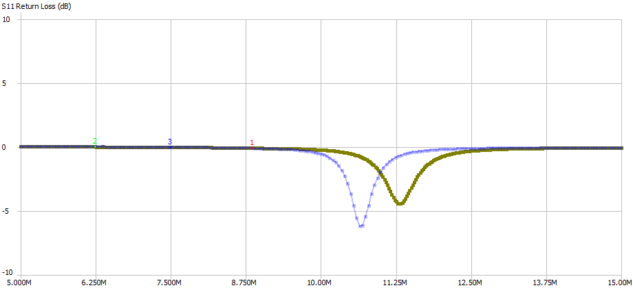
Sitting next to each other:
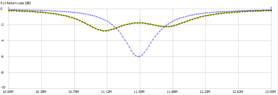
 <10dB of loss seems crazy good tbh. There’s also clearly a split in the S11 return loss peak so the antennas are influencing each other.
2m away
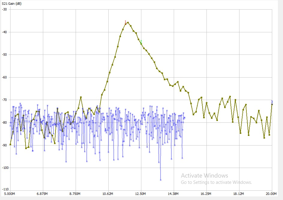
 S21 looks quite good but the S11 is clearly bad (should never be positive for a passive device!) and so perhaps it can’t be trusted.
Regardless I think we can try and transform the impedances now. The impedance of the antenna at the resonance point is acctualy quite real, 216+4.3JR. I suppose that’s energy transmission requires a real impedance.
S21 looks quite good but the S11 is clearly bad (should never be positive for a passive device!) and so perhaps it can’t be trusted.
Regardless I think we can try and transform the impedances now. The impedance of the antenna at the resonance point is acctualy quite real, 216+4.3JR. I suppose that’s energy transmission requires a real impedance.
50R matching.
Appendix H of the art of electronics is a good help here:
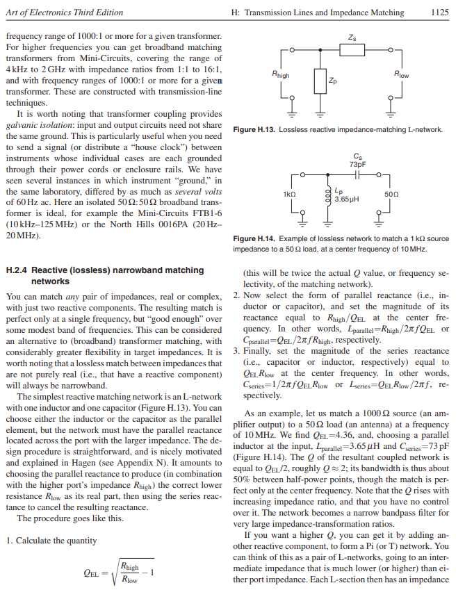 Matching to a 50R system means that our Qel is sqrt(200/50 - 1) = 1.73. So our inductor value should have an impedance of 200 / 1.73 = 113R. That means the value is 113/(2*pi*10e6) = 1.79uH.
Then we should have a capacitor with impedance 50 * 1.73 = 86.5R, or 183pF.
Let’s try it out!
I used two 910nH inductors in series and a 180pF capacitor to get this plot:
Matching to a 50R system means that our Qel is sqrt(200/50 - 1) = 1.73. So our inductor value should have an impedance of 200 / 1.73 = 113R. That means the value is 113/(2*pi*10e6) = 1.79uH.
Then we should have a capacitor with impedance 50 * 1.73 = 86.5R, or 183pF.
Let’s try it out!
I used two 910nH inductors in series and a 180pF capacitor to get this plot:
 With an impedance of:
 Absolutely spot on. Very high Q though.
The next day…
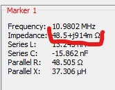
I come back the next day and measure this:
 49.9+6JR.
It seems like the resonant frequency moved by about 1MHz overnight, and the Q dropped as a result too!
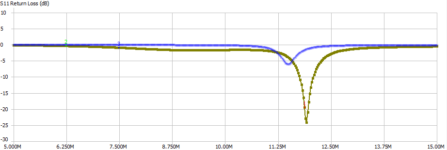
I don’t know why this would be. Taking the antenna off the bench and leaving it free hanging gives this plot:
49.9+6JR.
It seems like the resonant frequency moved by about 1MHz overnight, and the Q dropped as a result too!
I don’t know why this would be. Taking the antenna off the bench and leaving it free hanging gives this plot:
 Where the reference is on the bench and the poper measurement is off it.
This is terrible! The antenna bandwidth is going to shift around so much based on what it’s sitting next to the entire passband will move away!
Regardless let’s proceed with matching the other antenna and see if we get better transmission anyway.
…And after messing about with variable inductors trying to get things to line up I realise that it isn’t really possible to make a useable system with this. Tolerances in components and how the antenna is situated with respect to the other antennas etc just make too much difference. This is my first time measuring an antenna though so I shall go and make a proper 1/4 wavelength 915MHz antenna and see how sensitive that is to the environment.
Where the reference is on the bench and the poper measurement is off it.
This is terrible! The antenna bandwidth is going to shift around so much based on what it’s sitting next to the entire passband will move away!
Regardless let’s proceed with matching the other antenna and see if we get better transmission anyway.
…And after messing about with variable inductors trying to get things to line up I realise that it isn’t really possible to make a useable system with this. Tolerances in components and how the antenna is situated with respect to the other antennas etc just make too much difference. This is my first time measuring an antenna though so I shall go and make a proper 1/4 wavelength 915MHz antenna and see how sensitive that is to the environment.
”915MHz” antenna.
The antenna looks like this:
 And has an S11 that looks like this:
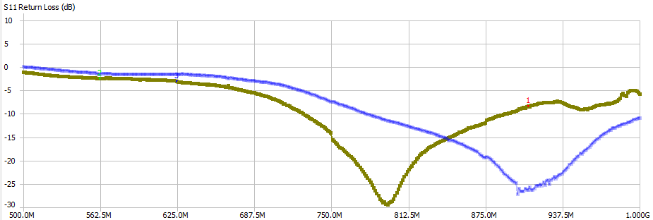 Where the two traces are with/without hand.
This is the smith chart:
Where the two traces are with/without hand.
This is the smith chart:
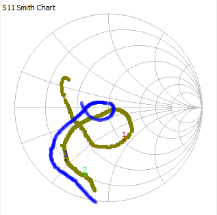 Overall this has made me thoroughly disillusioned with the whole antenna thing. Maybe consumer grade antennas are designed to be especially wideband to let in frequencies no matter how close/far the unit is to the meatbag? Unclear.