ird party plugins or themes, we highly encourage you to check for updates bFollowing the previous antenna tuning debacle it seems that a 10MHz antenna won’t work not because it doesn’t transmit necessarily, but because it’s passpand jumps around a lot based on what the antenna is next to. So the time has come to build a 915MHz oscillator and try and mix stuff in.
The only piece of equipment that I have that can detect 915MHz stuff is a RTL-SDR software defined radio. It will be hideously slow to sweep out a full spectrum, but should do the job.
Fortunately there is a great webpage on the topic which has just what I need. To minimise the chances of anything going wrong I will go with the high frequency oscillator that has the same topology as my current one:
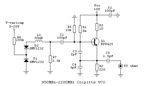 Which once it is working we should be able to adjust down to 915MHz no problem. I even have the BFP420 and some SMV1234 diodes.
This is what the circuit looks like assembled on the 20221015 FM V3 bringup pcb:
Which once it is working we should be able to adjust down to 915MHz no problem. I even have the BFP420 and some SMV1234 diodes.
This is what the circuit looks like assembled on the 20221015 FM V3 bringup pcb:
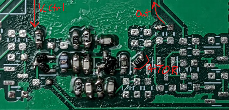 I used a 27nH inductor though.
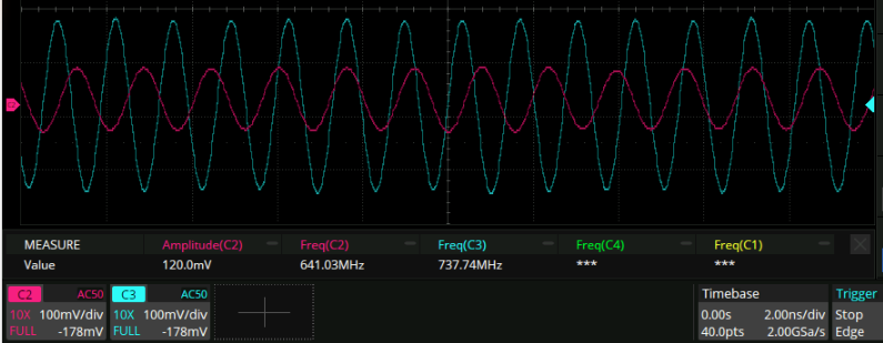
Straight out of the box it oscillates between and 520 and 730MHz! it’s only a 500MHz scope but it shows up great nonetheless:
I used a 27nH inductor though.
Straight out of the box it oscillates between and 520 and 730MHz! it’s only a 500MHz scope but it shows up great nonetheless:
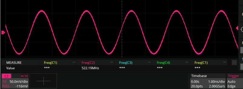 Assuming the signal is within the scopes frequency range that would put the amplitude at about 1.5V, too. I guess this guy really knows what he’s doing.
The circuit only has a 730/520 = 1.5:1 tuning ratio though compared to the claimed >2:1. not sure what the cause of that is. Could well be parasitics, since we are talking about single digit pF here.
Apparently the frequency of oscillation in the above circuit is given by ω2 L = 1/(C2+Cvar)+(1/C3)+(1/C4). So since I want a frequency 50% higher that means I should divide the L by 1.5^2 = 2.25, right?
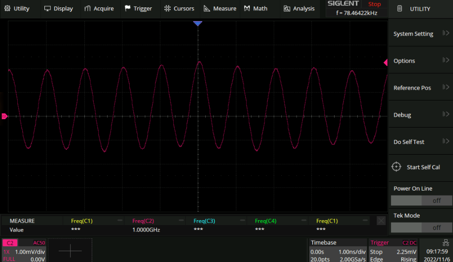
Swapping out for a 12nH inductor gives a low frequency of 720MHz and a high of something that is north of 1GHz (this is a 2GSa/s scope):
Assuming the signal is within the scopes frequency range that would put the amplitude at about 1.5V, too. I guess this guy really knows what he’s doing.
The circuit only has a 730/520 = 1.5:1 tuning ratio though compared to the claimed >2:1. not sure what the cause of that is. Could well be parasitics, since we are talking about single digit pF here.
Apparently the frequency of oscillation in the above circuit is given by ω2 L = 1/(C2+Cvar)+(1/C3)+(1/C4). So since I want a frequency 50% higher that means I should divide the L by 1.5^2 = 2.25, right?
Swapping out for a 12nH inductor gives a low frequency of 720MHz and a high of something that is north of 1GHz (this is a 2GSa/s scope):
 Excellent! Only one problem - I only bought two of those diodes so I can’t make another receiver circuit straightaway. To digikey!
Mixing
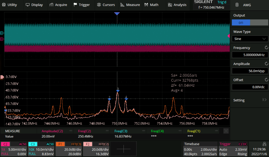
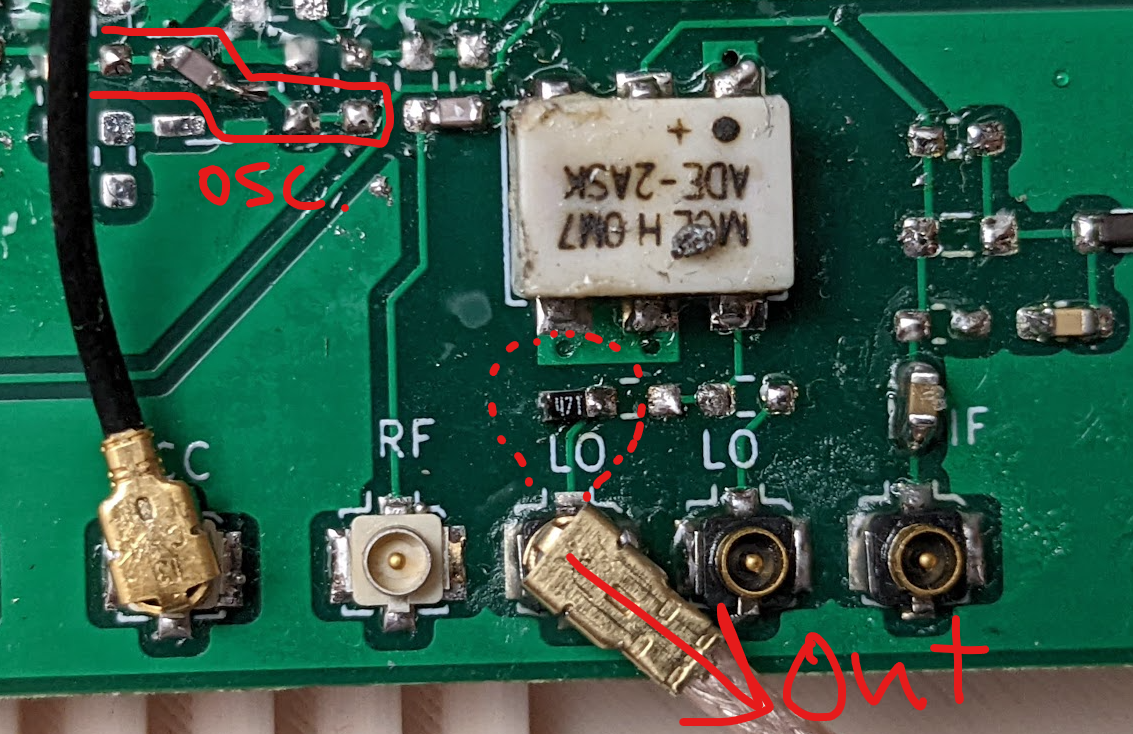
Next step is to do the upconversion. Since it turns out my scope can see 720MHz just fine, let’s do it there. The seupt is the output of the oscillator tuned to 750MHz on the dot sent into an ADE-2ASK+ mixer as the “LO”, with the “IF” being a 5MHz sin wave coming from the function generator (amplitude only 56mV here).
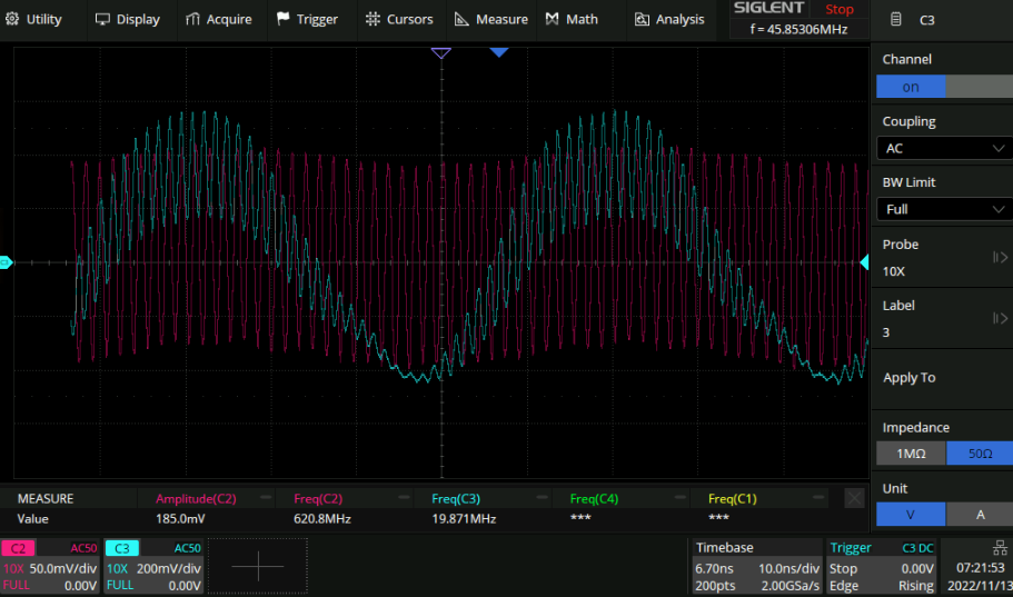
Here is an FFT of before mixing (white) and after mixing (orange):
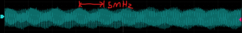
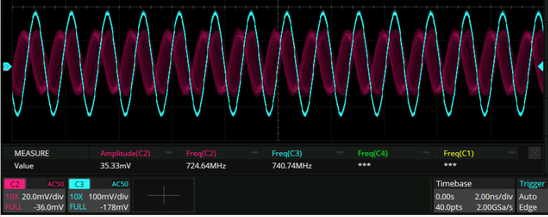
 If we zoom in on the time series we can see the modulation of channel 3:
 I don’t know what the deal is with the three spikes in the frequency domain. This is outside the proper operating region of the scope so it might just be a measurement thing but if not this is something to worry about I think.
This all looks fairly reasonable, now the question is if it can be downconverted back to the original signal.
Handy graph for what things go where
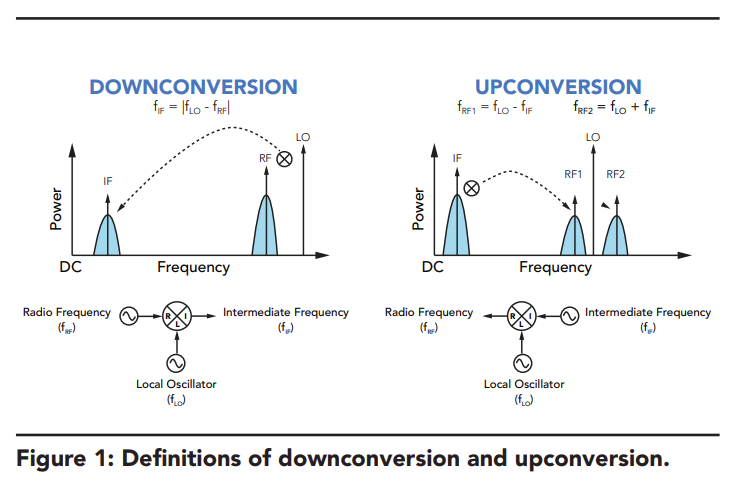 From here.
Pinout that infineon was too lazy to make
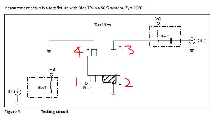 BFP420H
Oscillator 2
I made this one out of an old FM V2 PCB because it still had the footprint for the ADE-2ASK+ mixer on it. Here are the two outputs side by side with the same varactor voltage:
 Why is the second oscillator so much lower than the first? Well because it isn’t actually wired up to the output of the oscillator:
 And it still gets that much signal!
Actually wiring it up and making sure that I am measuring the same thing for both oscillators doesn’t actually seem to change anything. In addition to this the amplitude falls off super fast with increasing frequency so by the time I am tuned up to the range of the first oscillator the amplitude is very low. It does form a spontaneous PLL though, which is cool:
And it still gets that much signal!
Actually wiring it up and making sure that I am measuring the same thing for both oscillators doesn’t actually seem to change anything. In addition to this the amplitude falls off super fast with increasing frequency so by the time I am tuned up to the range of the first oscillator the amplitude is very low. It does form a spontaneous PLL though, which is cool:
 I don’t know why this amplitude fallin off thing is happening. I checked the DC levels everywhere and didn’t find anything. I double checked and replaced the feedback capacitors and they are fine.
Interestingly probing the emitter of the transistor with a multimeter lead has very different results. For the well behaved circut the results look like thiss:
I don’t know why this amplitude fallin off thing is happening. I checked the DC levels everywhere and didn’t find anything. I double checked and replaced the feedback capacitors and they are fine.
Interestingly probing the emitter of the transistor with a multimeter lead has very different results. For the well behaved circut the results look like thiss:
 I interpret this to mean that the impedance the emitter sees to ground kind of moves around with frequency because the multimeter lead is a transmission line or whatever. This effect disappears when I touch ground with my other hand btw.
… This whole thing turned out to be the AC coupling capacitor coming out of the oscillator being desoldered on one end :shrug:.
I interpret this to mean that the impedance the emitter sees to ground kind of moves around with frequency because the multimeter lead is a transmission line or whatever. This effect disappears when I touch ground with my other hand btw.
… This whole thing turned out to be the AC coupling capacitor coming out of the oscillator being desoldered on one end :shrug:.
Mixing again
Putting a 10KHz square wave into the 10MHz VCO which then gets upconverted in the 750 MHz VCO like so:
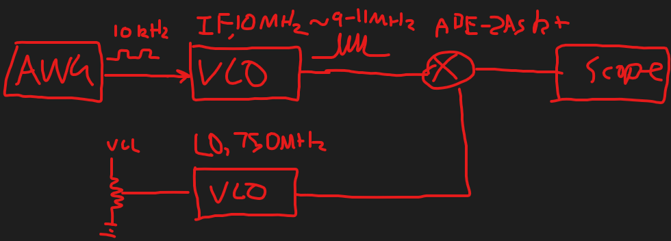 I tuned the high frequency to be at 750MHz rather than 915MHz cause that was what was easy to do at the time.
This results in the following spectrum:
I tuned the high frequency to be at 750MHz rather than 915MHz cause that was what was easy to do at the time.
This results in the following spectrum:
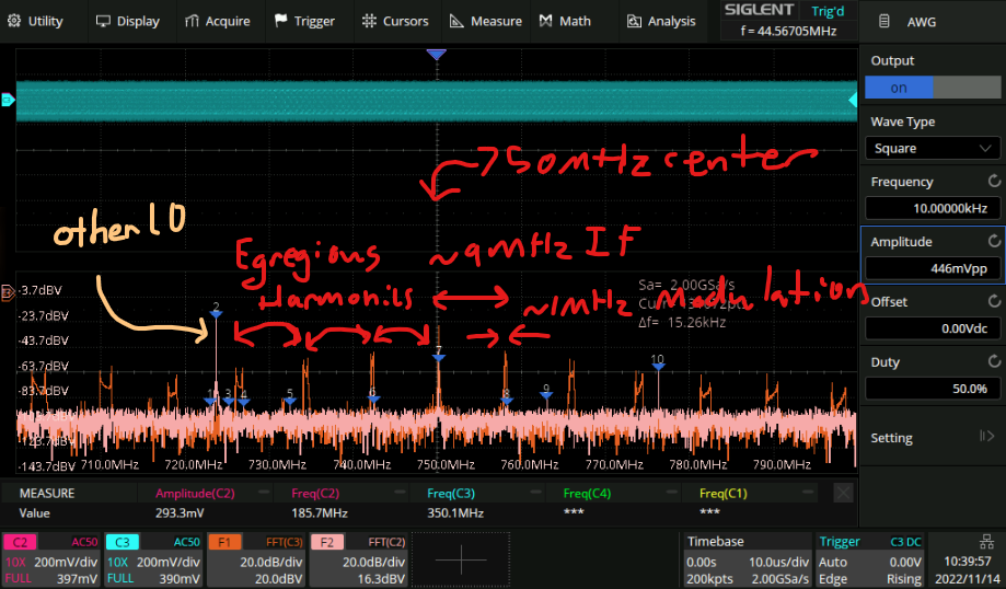 Looks pretty reasonable to me, now to take that output and put it into the next mixer to downconvert it. This is the part that should theoretically cross the air gap to the headphones.
Results of downconversion:
Unforturnately it looks like if I put the two LO’s at the same 750MHz frequency they just phase lock:
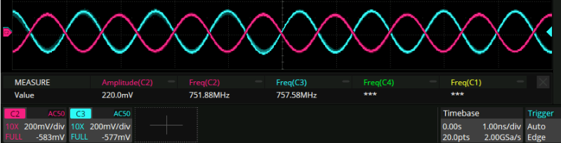 …That’s not what I want. Right?
I think the next version of my board should include a usb connector to make it easier to power the things separately, and a long way away from the bench.
I think I will adjourn here and make that pcb. Parasitics and whatnot are bound to be important so I may as well order it now.
…That’s not what I want. Right?
I think the next version of my board should include a usb connector to make it easier to power the things separately, and a long way away from the bench.
I think I will adjourn here and make that pcb. Parasitics and whatnot are bound to be important so I may as well order it now.