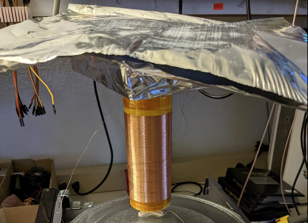
The coil
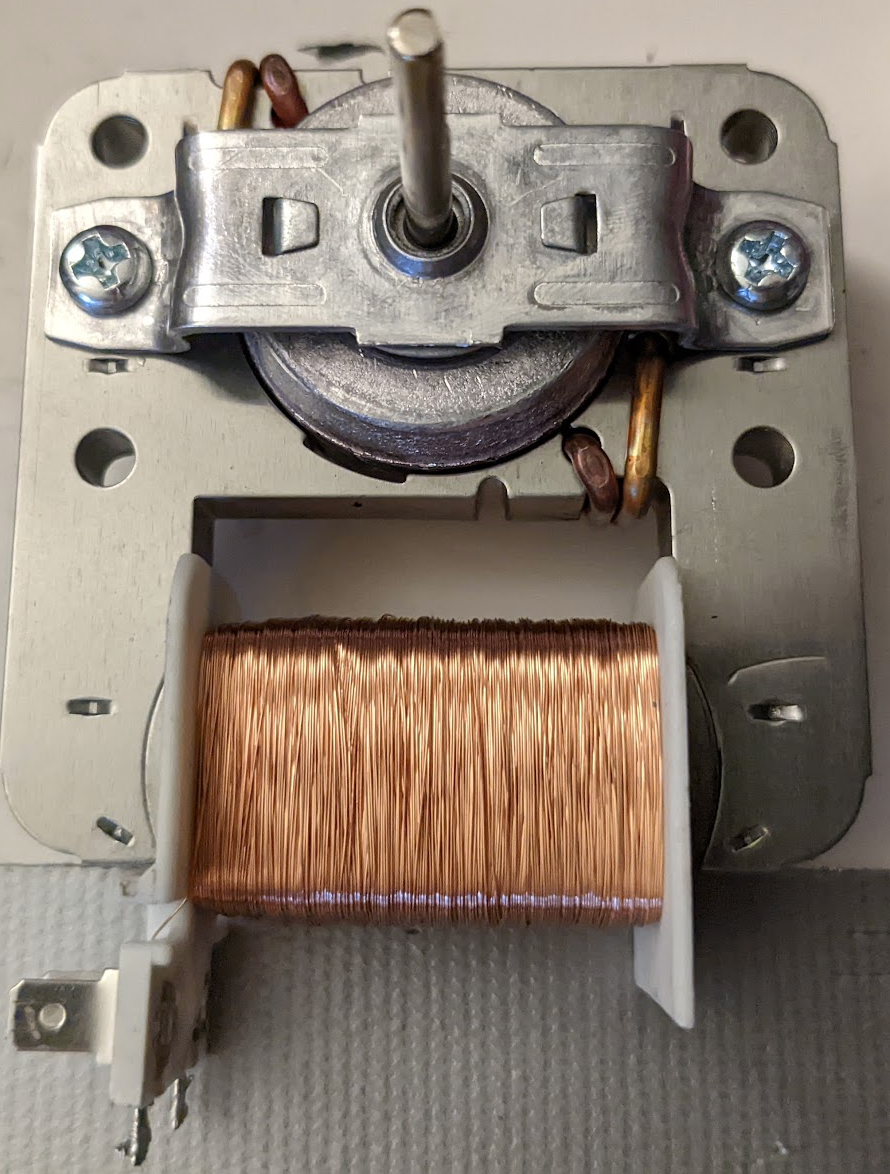
Wound from the fan motor:
Into this:
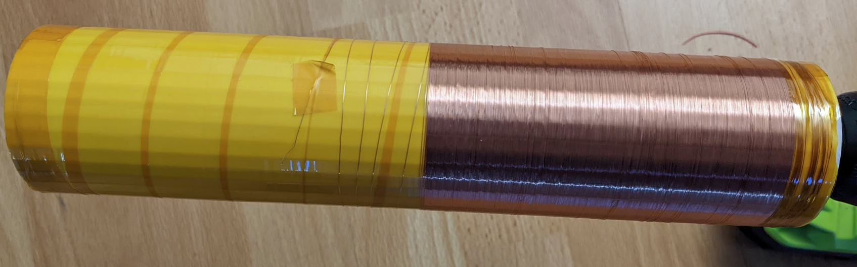
…misjudged the amount of wire a bit.
Inductance measurement:
Here is the R+Jx plot a la from 20220701 Inductance measurements:
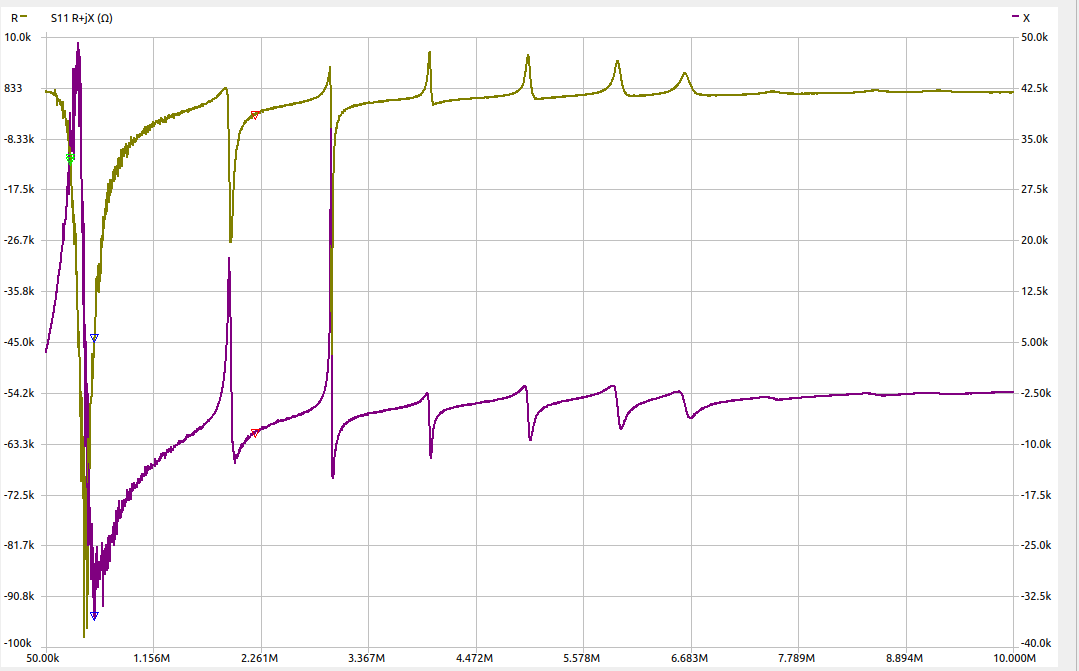
I don’t know what this means really but those are some big numbers and thin spikes!
Resonance thereof
The planned schematic of the tesla coil goes something like this:
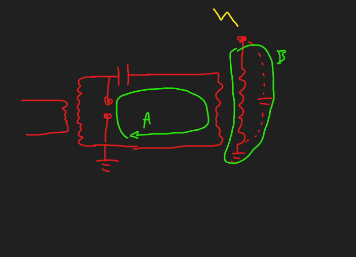
Here LC circuit A must of course be matched in resonant frequency to LC circuit B for maximum energy transfer and whatnot. Since the VNA only goes down to 50KHz I decided to make this circuit to measure the resonant frequency:
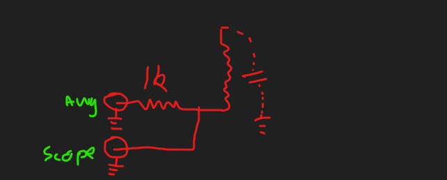
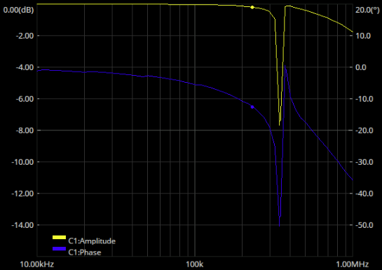
When we do a frequency sweep there should be a sharp drop in amplitude measured by the scope. Fortunately this seems to have worked great, here’s a bode plot from the scope of circuit B:
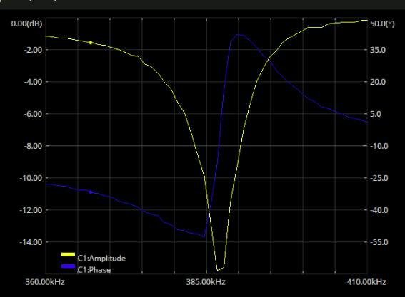
387KHz is pretty high for a tesla coil I believe but then again it’s a small coil. By the way I disconnecte the scope from the measurement and the dip went away, so this is definitely a measurement of the coil. The measurement setup looks like this:
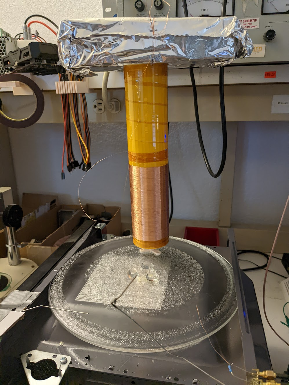
With the probes just barely visible in the corner.
Circuit A
This one was probed like so:
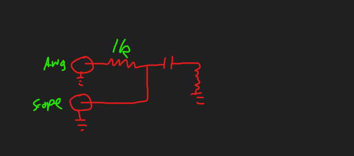
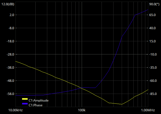
Which yielded this plot:

Resonance at 65KHz, and wayyy lower Q in this plot. I think it’s supposed to be like that though, lookss like a classic “capacitor down 20dB/dec + inductor up 20dB/dec”. Who knows why the other one is higher Q, then. The capacitor was a 0.75uF+-3% one rated to 2100V. Resonant frequency of a LC circuit is: And so with a capacitance of 0.75e-6 and freq of 65e6 that gives us an L of 8H exactly. That seems rather high…
Resonant frequency adjustments
The primary side has the resonant frequency of 65kHz, the secondary 387KHz. Gotta make them meet. Adding a hat to the tesla coil:
Moves the frequency from 430KHz to 380KHz:
(Why did the frequency go up again? idk)
Here is the plot of the microwave oven capacitor straight to ground:
Since the minimum impedance here is already around 300KHz. Any turns on the secondary at all will just pussh that down more. Not much hope, then.