Idea
I would like to 3d print some propellers. Propellers have a tendency to flap about, so it would be good to film them to see if that’s happening. But you can’t do that with a regular camera.
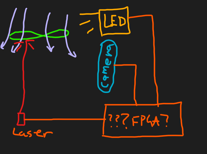
Solution: a strobe camera. I have a realsense camera D435i that has a strobe input, so that combined with a flashy LED thing should get me what I need.
Flashy bit
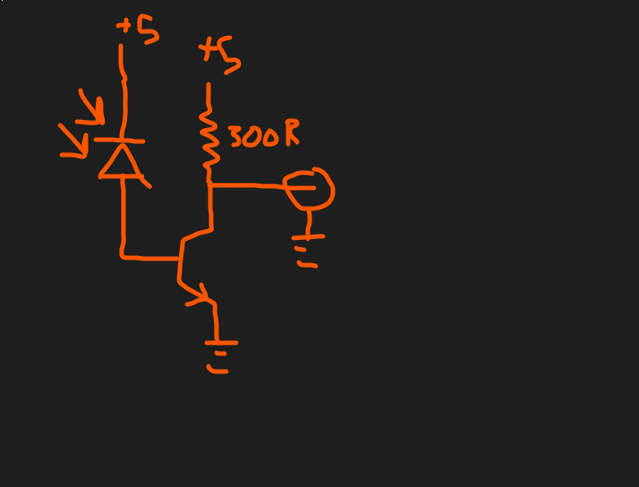
I tried to Make some more pcbs but it seems the developer solution has gone off so I went and found MikesElectricStuff’s guide on pcbs and bought some sodium silicate. In the meantime I will use the Bang1 circuit to drive my COB LED like so:
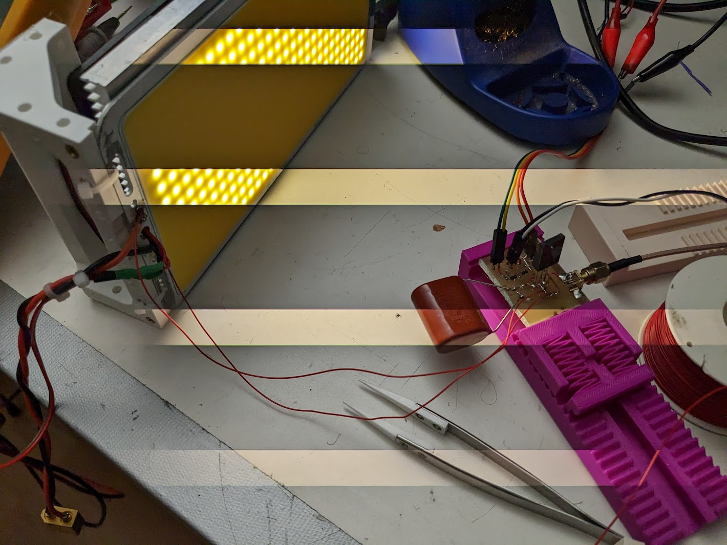 We can see that the strobing is working rather well!
Here is a more quantified measurement of the light output:
We can see that the strobing is working rather well!
Here is a more quantified measurement of the light output:
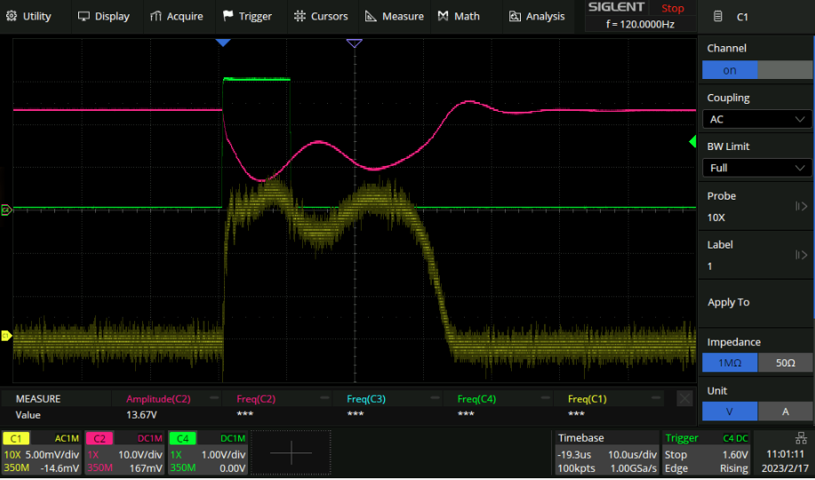 Green = pulse trigger. Red = drain of the FET. Yellow: 1k resistor from 5v biased photodiode to ground.
Output
Here is an image of a propeller spinning at 50Hz or so:
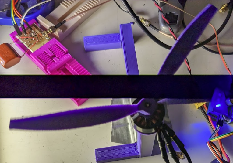 The bars are cause there were a couple of strobes over the camera exposure time (phone camera).
Measuring
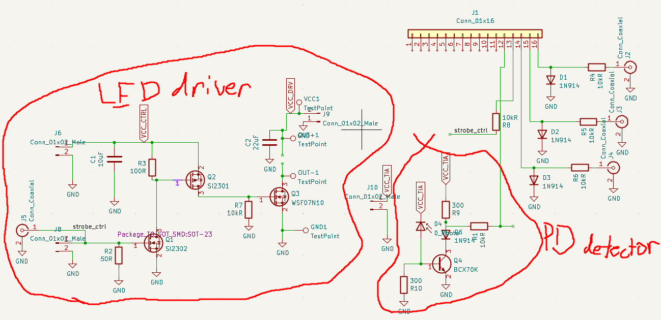
The next step is to bounce a laser off the propeller and measure what comes back to phase lock tothe propeller. I had the brilliant idea to use a solar panel instead of a photodiode for that phat detection area, no lens required.
Here is my detection circuit:
 and irl:
Only one problem: It’s a nice 90MHz oscillator:
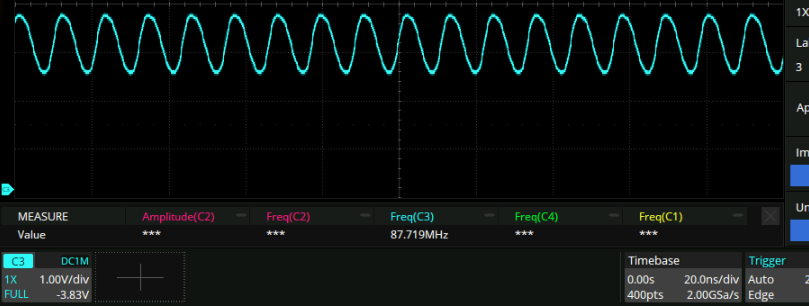 This oscillation seems dependent on the ambient light level and also the supply voltage. On further inspection this is cause I attached the cathode of the solar panel to the collector of the transistor. Also, it seems that there is a fair bit more sensitivity if you just attach the solar panel anode to ground and cathode to the base of the transistor. Maybe solar panels aren’t photodiodes after all?
Wait
Actually this whole idea is dumb. Since I have my own test setup I can just point the light from one side of the propeller to the other. Or stick a retroreflector on the ceiling, or something.
PCB setup
Here is what I came up with:
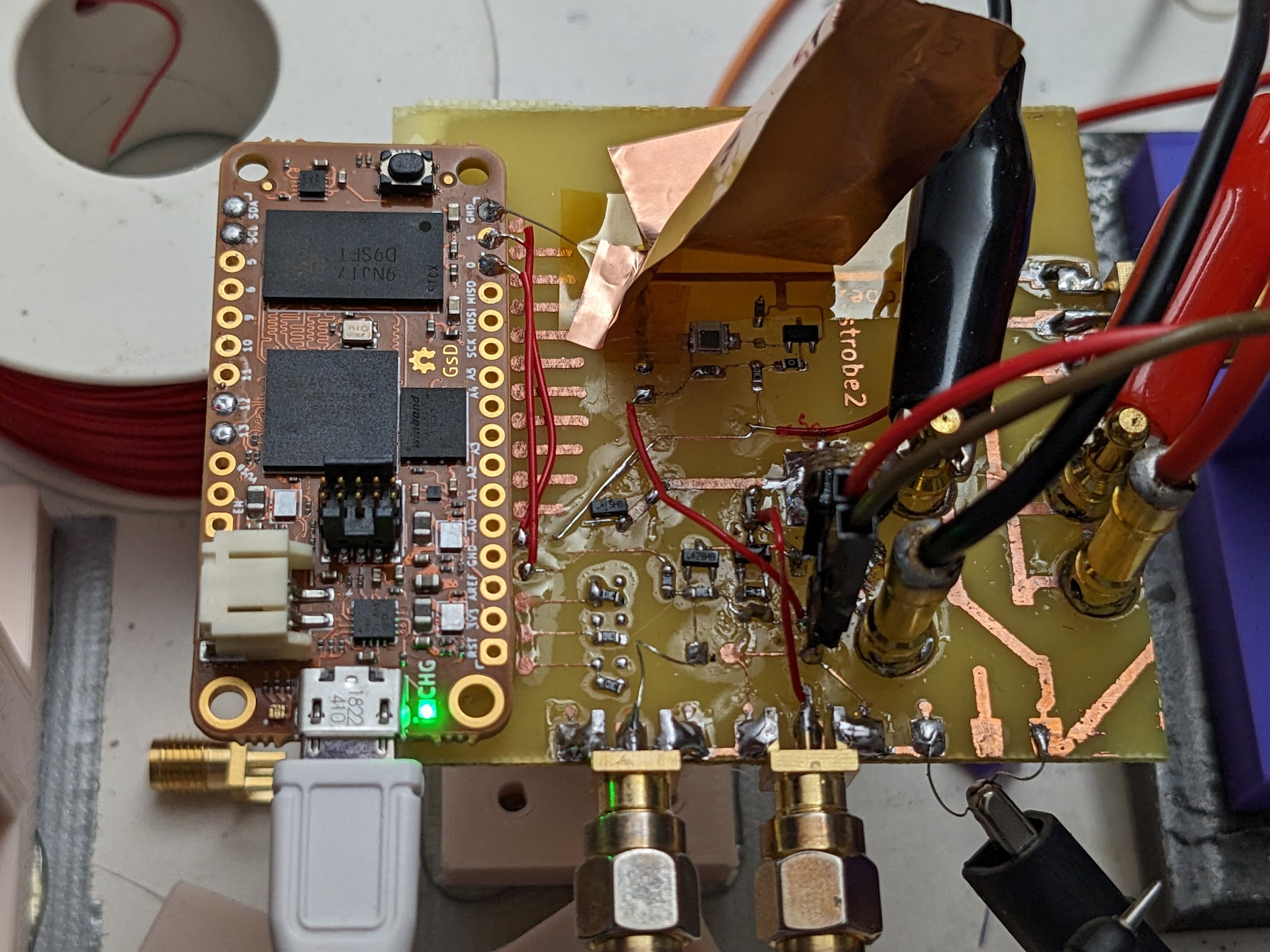 Tad bit of trouble getting things up and running but it’s going nicely now. The photodiode is the rectangle being shielded by the copper tape from the light coming from the LED.
Results are looking good. Pretty hard to photograph. Quick calcs about how long to make the pulse. let’s say we want 0.1mm of blurring. Prop radius = 80mm ⇒ circumference 500mm. Prop goes past every 8ms. so we want an exposure time of 0.1 / 500 * 8 = 1.6us. That’s pretty short! I have the fpga emitting a 5us pulse and that results in this waveform:
Tad bit of trouble getting things up and running but it’s going nicely now. The photodiode is the rectangle being shielded by the copper tape from the light coming from the LED.
Results are looking good. Pretty hard to photograph. Quick calcs about how long to make the pulse. let’s say we want 0.1mm of blurring. Prop radius = 80mm ⇒ circumference 500mm. Prop goes past every 8ms. so we want an exposure time of 0.1 / 500 * 8 = 1.6us. That’s pretty short! I have the fpga emitting a 5us pulse and that results in this waveform:
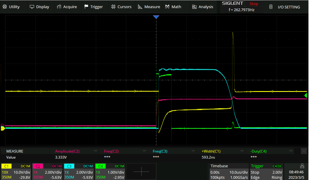 yellow = MOSFET drain, Pink = optical propeller detector, Blue = MOSFET gate, Green = FPGA trigger out.
So unless I want to mess about with the driving circuit this is about as good as it’s going to get I think. Should keep an eye on the Yuge spike in the supply voltage too.
yellow = MOSFET drain, Pink = optical propeller detector, Blue = MOSFET gate, Green = FPGA trigger out.
So unless I want to mess about with the driving circuit this is about as good as it’s going to get I think. Should keep an eye on the Yuge spike in the supply voltage too.