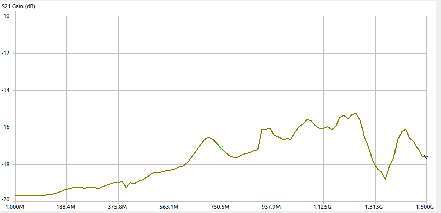
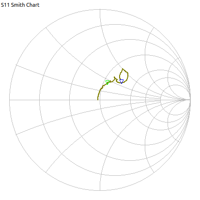
Now that I have obtained a spectrum analyser, work can continue on the radio from earlier. The reason that things stalled before was that I was unable to get a good measurement of the gain of an amplifier. Now I didn’t obtain a proper VNA which would have ideal, but I did get a screaming deal on a 10MHz→4.4GHz spectrum analyser.
The analyser only has one input with a max input power of 0dBm though so we’ll see how long it lasts before I cook it.
Because of this limitation the first order of business is making some attenuators to keep everything in range. Here is the first one:
Looking at a known signal.
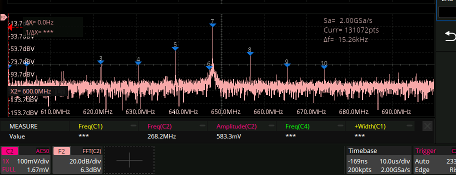
Here is what the FFT of the nanoVNA is when it’s outputting a CW “750MHz” signal according to my scope:
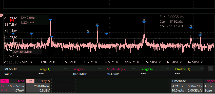 This is cause it uses all kinds of harmonics to get the performance at higher frequencies. Here is what the same signal looks like on the spectrum analyzer:
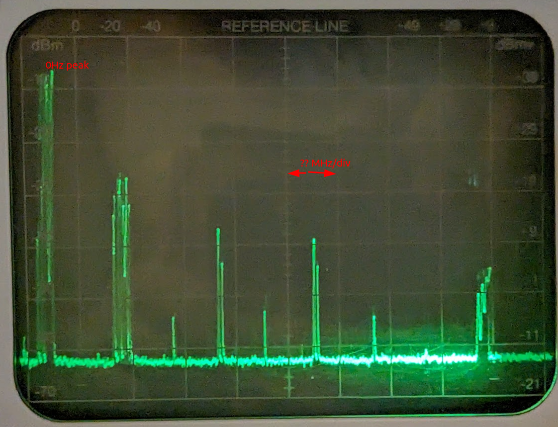
And this is what my VCO (with extra capacitance to try to bring down the frequency) looks like:
 (note the x axis here)
with the spectrum analyser:
(note the x axis here)
with the spectrum analyser:
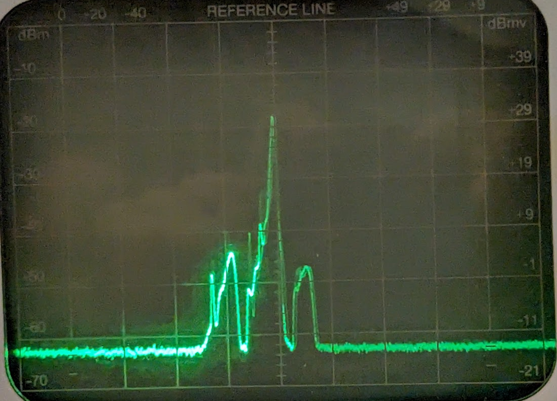 The display in the top left (not in pic) agrees with the peak wavelength. But it looks like this is not very good at picking up the harmonics or anything else.