So far
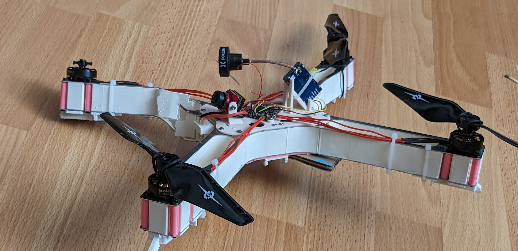
Drone assembled:
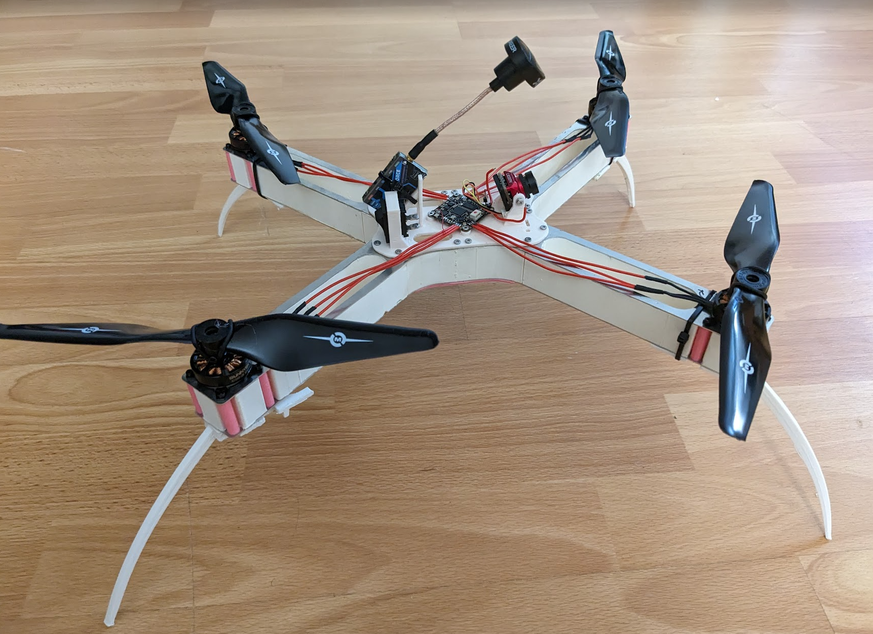 and flying at about 380g. It flies OK but I think I need to tune the PIDs. Only one problem, on my last flight this happened:
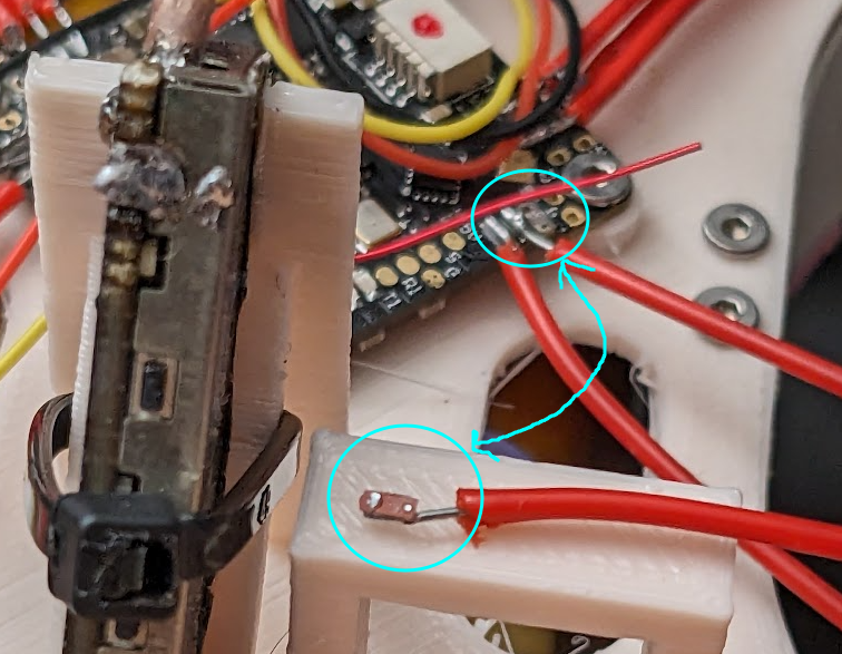 And now one of the motors doesn’t work well (after soldering the motor wire through the via to the pad on the other side of the board). It can spin up no problem at low speed, but at high speed it loses thrust and starts oscillating, I don’t know why.
Debugging
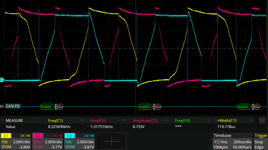
Here is an oscilloscope trace of a normal motor phase:
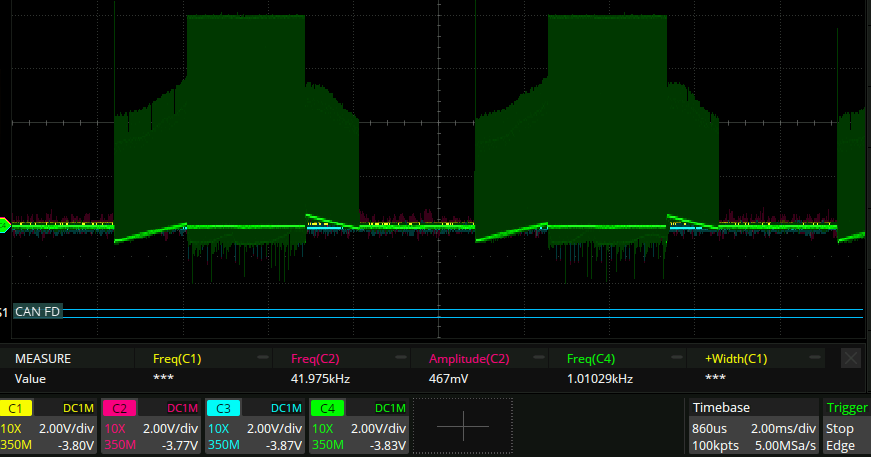 Where you can see that regular trapezoidal pattern. All the motor phases for a normal motor look like this.
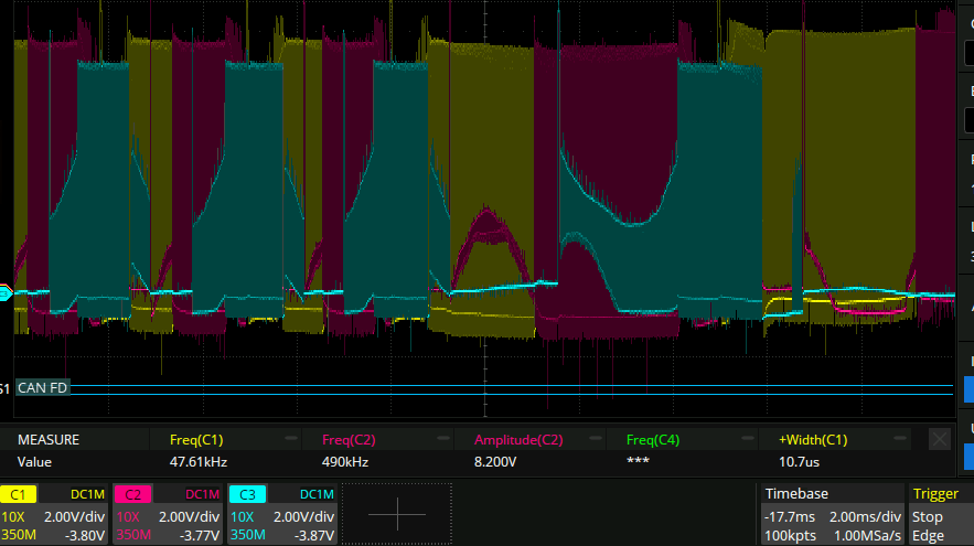
And here are the three motor phases for the bad motor:
Where you can see that regular trapezoidal pattern. All the motor phases for a normal motor look like this.
And here are the three motor phases for the bad motor:
 We can see here that only one of the phases has that trapezoidal shape. All the other ones are plain square waves.
A further piece of information: the busted motor phase of the bad motor is not fully disconnected: if I desolder it completely the motor doesn’t spin up at all. So I wonder if what is happening is that either the p or the n FET of that half bridge is busted. This theory is bolstered by how there is a second via inside the pad of the motor phase that had the pad ripped off. One of the vias is large and I can fit a wire into it to solder to it. The other is small and I can’t. I wonder if the small via leads to the other polarity FET.
…This turns out not to be the case. soldering the motor phase to only one of the vias produces the same effect as soldering to both. Also they are shorted together
We can see here that only one of the phases has that trapezoidal shape. All the other ones are plain square waves.
A further piece of information: the busted motor phase of the bad motor is not fully disconnected: if I desolder it completely the motor doesn’t spin up at all. So I wonder if what is happening is that either the p or the n FET of that half bridge is busted. This theory is bolstered by how there is a second via inside the pad of the motor phase that had the pad ripped off. One of the vias is large and I can fit a wire into it to solder to it. The other is small and I can’t. I wonder if the small via leads to the other polarity FET.
…This turns out not to be the case. soldering the motor phase to only one of the vias produces the same effect as soldering to both. Also they are shorted together
The moment of failure
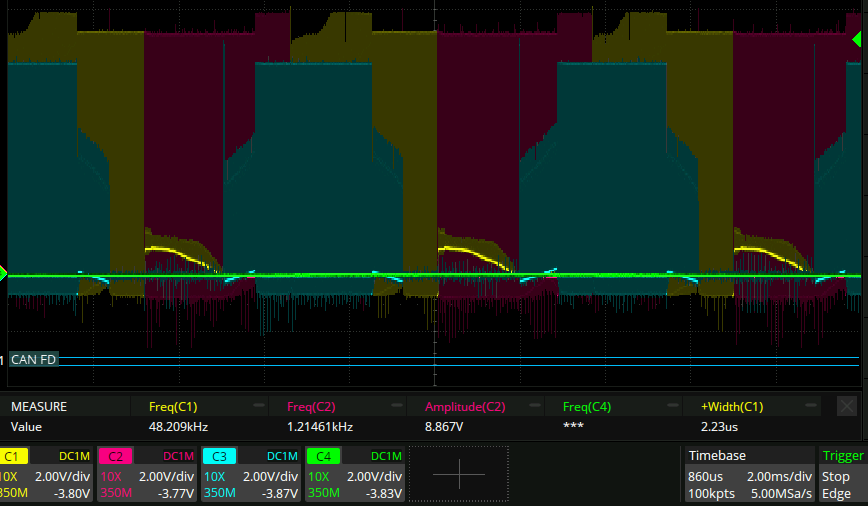
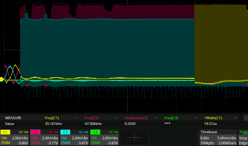
Here is what the motor phases look like when they go from commutation properly to juddering:
 Here Channel 2 (purple) is the ad motor phase.
I don’t know what this means. I think though that the purple arc might be the back emf more than anything else.
Here Channel 2 (purple) is the ad motor phase.
I don’t know what this means. I think though that the purple arc might be the back emf more than anything else.
 I took the propeller off the motor and spun it up to full speed no prolem. This is what the waveform looks like. A bit misshapen, but nothing obviously bad. Occasionally when spinning up the motor with no load, it loses commutation in a manner similar to when it has a propeller attached. Here is an example of that happening:
side note
The antenna on that AIO is 32mm long and made of 0.4mm enameled wire.
The resolution
After some more debugging where I measured the FETs of the half bridge (diode drops and resistance) and found them to be totally normal I did the obvious thing that I should have done ages ago and swapped the motor to a different ESC. Turns out it was the motor.
I had no idea it was possible for a visually perfect, no grinding when spinning, even resistance between phases motor to give unreliable performance like that. Oh well.
The crash
The drone now looks like this:
 which as far as I could tell came as a result of the controllers freaking out when I tried to pull out of a fast(ish) turn. The PID’s had not been tuned at all, so that one is on me I guess. I only had parts spare for one arm but two were broken in this crash, so now might be a good time for a redesign.
One other thing to note was that I had previously broken off a bunch of the legs so there was no crumple zone. The next design should have more of that I think. The current legs aren’t good at absorbing shock too I feel.
In the next design I’m not sure whether to add more durability or more manufacturability. I think the latter. There’s not really any such thing as a durable drone when it’s this lightweight though. (or is there? maybe some super thin carbon fiber?)