Note: Actually I’m using OrcaSlicer. There doesn’t appear to be much difference in practice.
Problem
You have a structural part that you would like to
- Be strong
- Be light. Like this drone arm, for example:
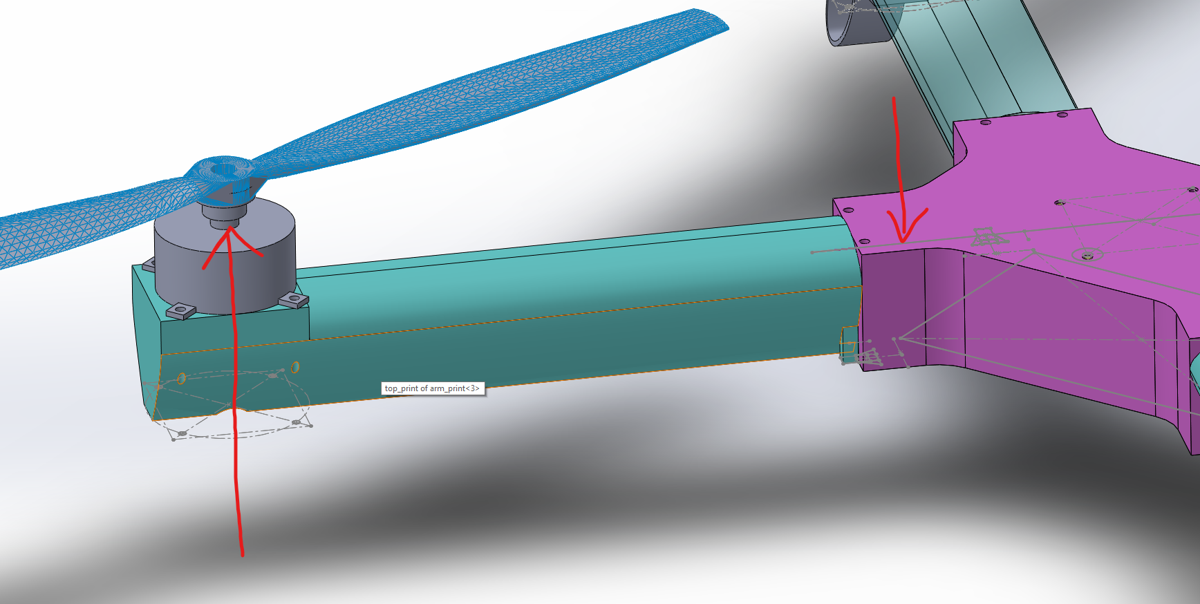
Taking a closer look at where the drone arm joins the body:
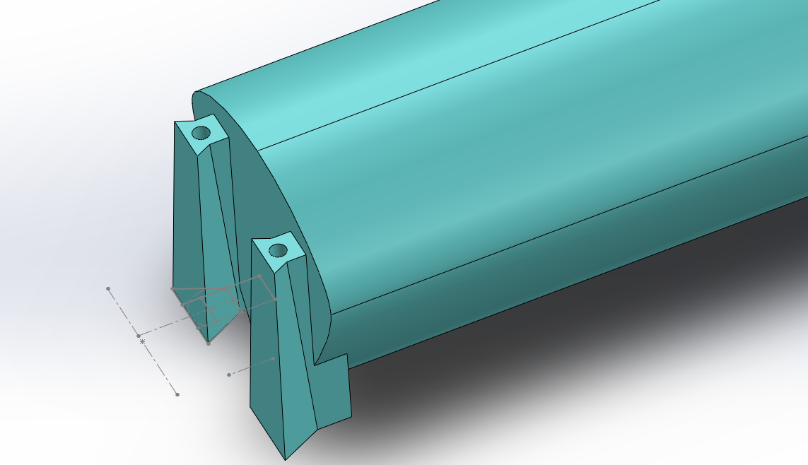
Obviously there are going to be very concentrated loads where the dovetail meets the arm. When you slice the arm it looks like this by default in the slicer:
This is clearly wildly inappropriate. We would like to print a bunch of support ribs on the inside so it is nice and strong, like this:
(That’s an earlier model with one dovetail)
Bambu lab/Orca slicer/Prusa slicer ‘regions’
I communicated this to cura slicer no problem by placing voids at the right locations in solidworks. If you try this in Bambu lab it fails miserably, there seems to be some kind of issue printing stl files with inclusions.
There is a better way though - Bambu lab has provisions where you can combine different stl files together and give them different properties. You can two this in one of two ways that are relevant here, where one STL file is the plain drone arm and another are the support ribs or whatever that you wish to add.
- Have the support STL be a ‘negative part’
- Have the support STL be a ‘modifier’. Following on from what worked in the cura slicer you would think that the first option is what you want. But no. The bambu studio will generate a pile of junk around the bottom of the supports that add weight:
Here we can see both the unnecessary junk and also the new nasty thing - the slicer will tend to route perimeter lines continuously which will split up the support ribs. As far as I can tell both of these things are insurmountable in the ‘negative part’ mode.
Instead what we can do is have the support STL be a ‘modifier’, and then have those sections of the arm printed with 100% infill. This works much better. There are two types of infill though - solid infill and sparse infill. If you print with solid infill you will get something like this:
Where the ‘supports’ don’t actually attach to anything. If you print with ‘sparse infill’ you can get something like this:
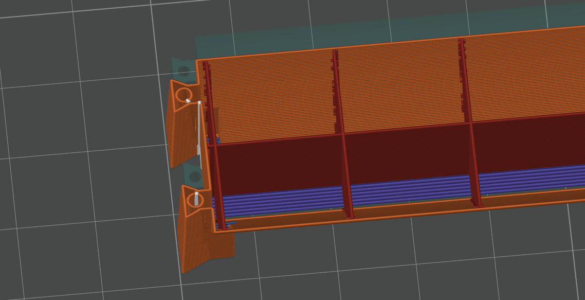
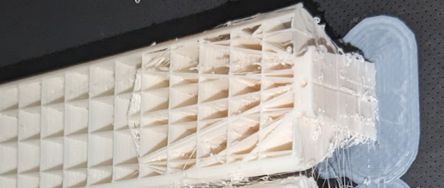
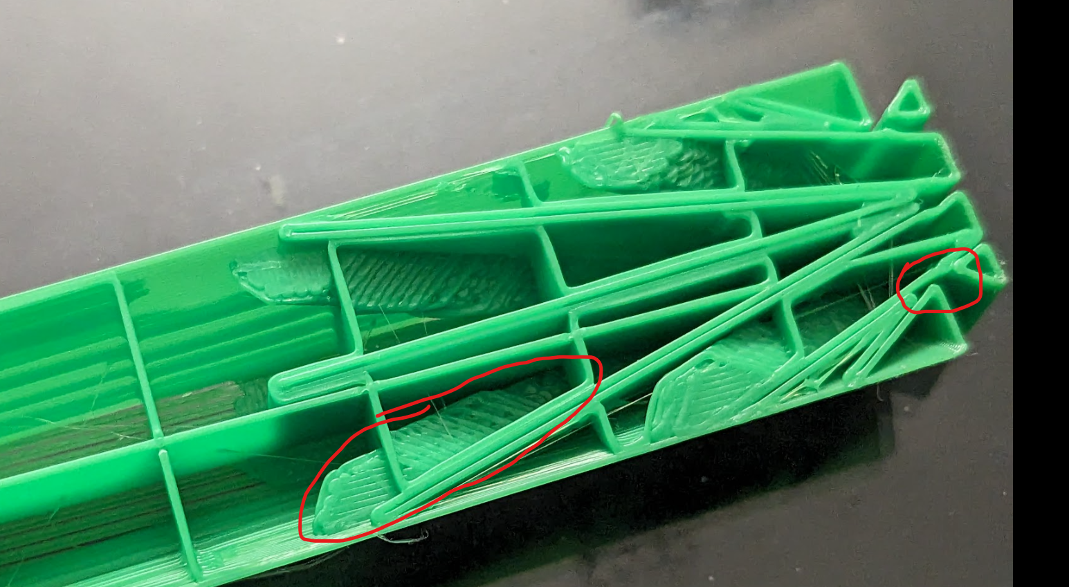
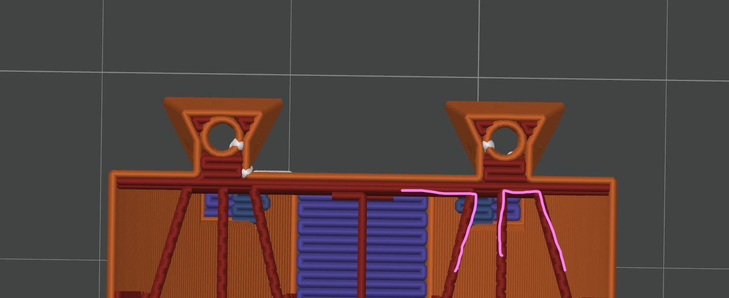
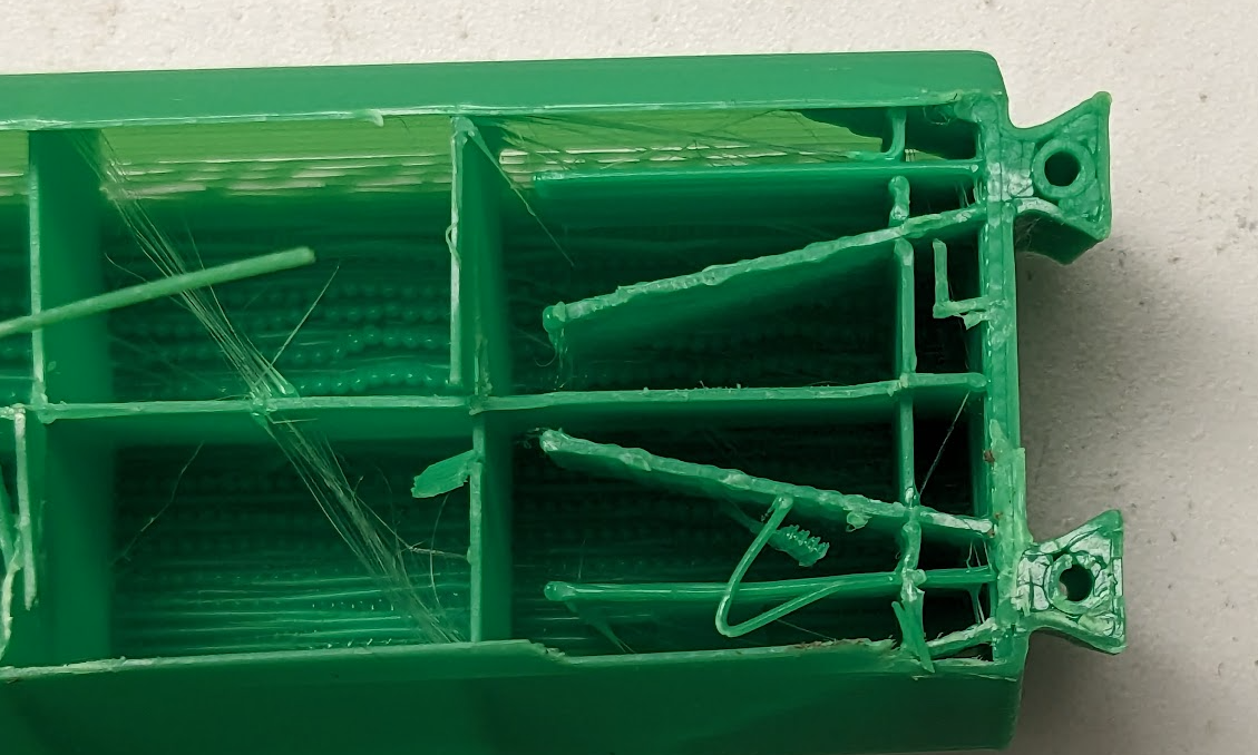
which is kind of better, but again not great. Based on the above results I added a third modifier STL that just covered the volume of the dovetail since that was the weak point. Here is what that looks like in the slicer and printed out:
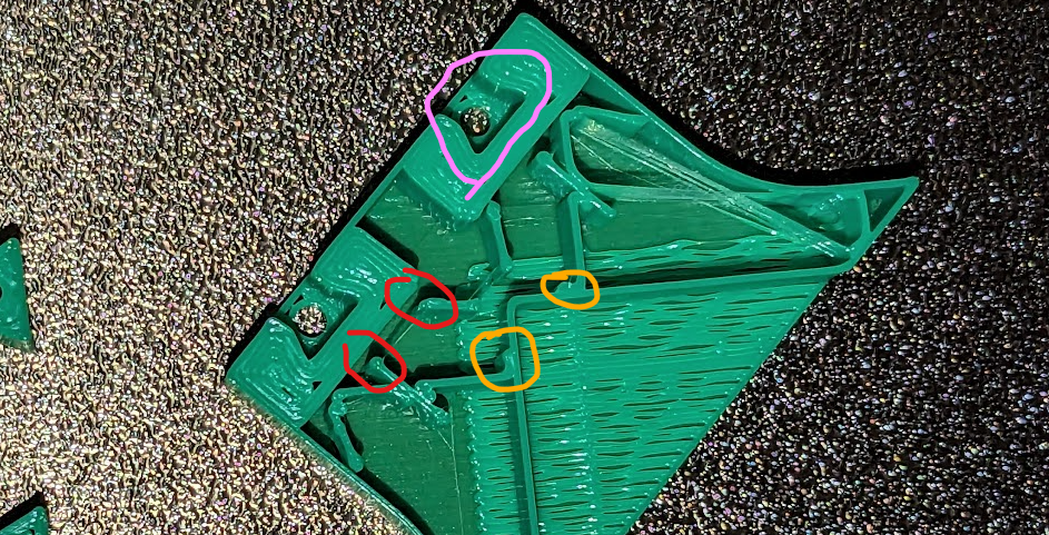 In red here we can see that the sparse infill still doesn’t attach to the part that we want on the dovetail. It does attach quite well however to the actual perimeter wall (orange). And we can see in purple that the 100% infill worked pretty well.
A side note here for people actually printing - two very relevant settings are the ‘minimum sparse infill threshold’ and the ‘maximum length of the infill anchor’:
In red here we can see that the sparse infill still doesn’t attach to the part that we want on the dovetail. It does attach quite well however to the actual perimeter wall (orange). And we can see in purple that the 100% infill worked pretty well.
A side note here for people actually printing - two very relevant settings are the ‘minimum sparse infill threshold’ and the ‘maximum length of the infill anchor’:
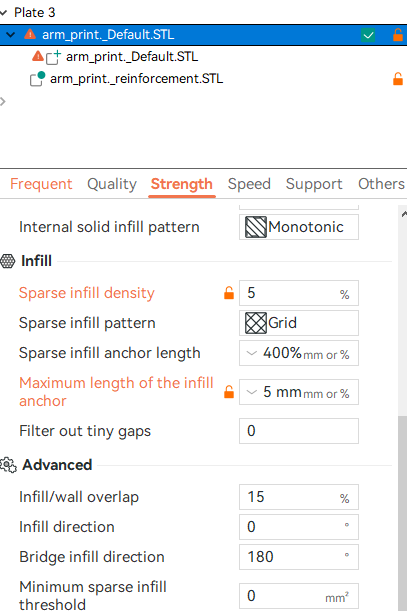 The former in particular can be set to a very high value on a modifier stl so that the part is converted entirely to solid.
Both sparse
—At this point my notes have caught up with my progress—
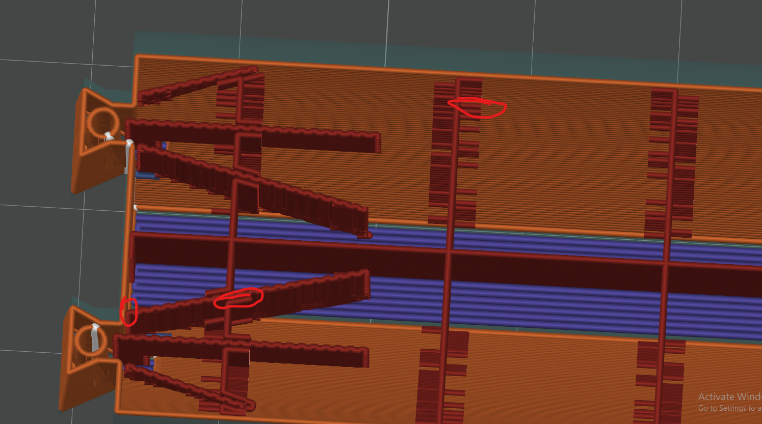
Here is what happens when you make both the supports and the infill area sparse:
 ta-da! This looks very promising - contiguous lines are made between the support struts and the base. I shall print this right away!
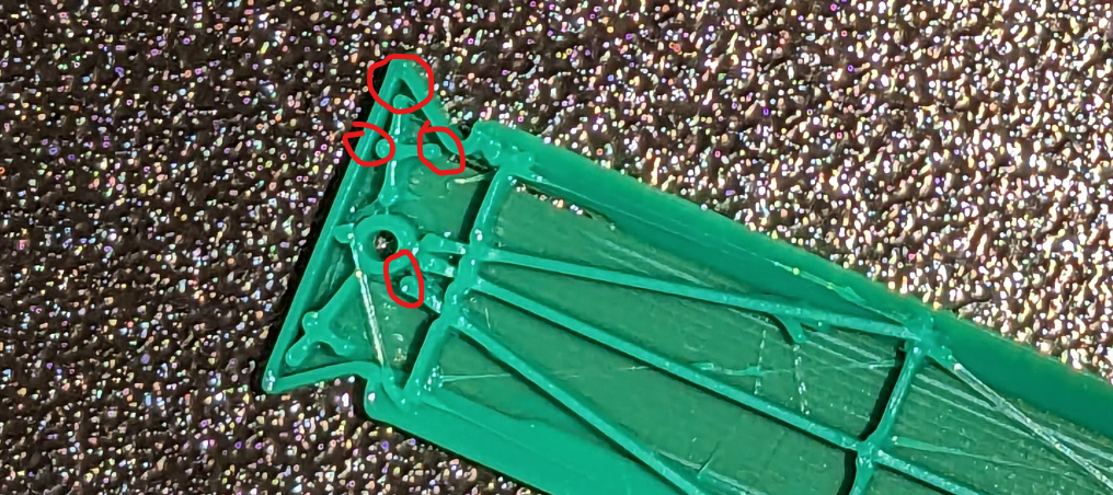
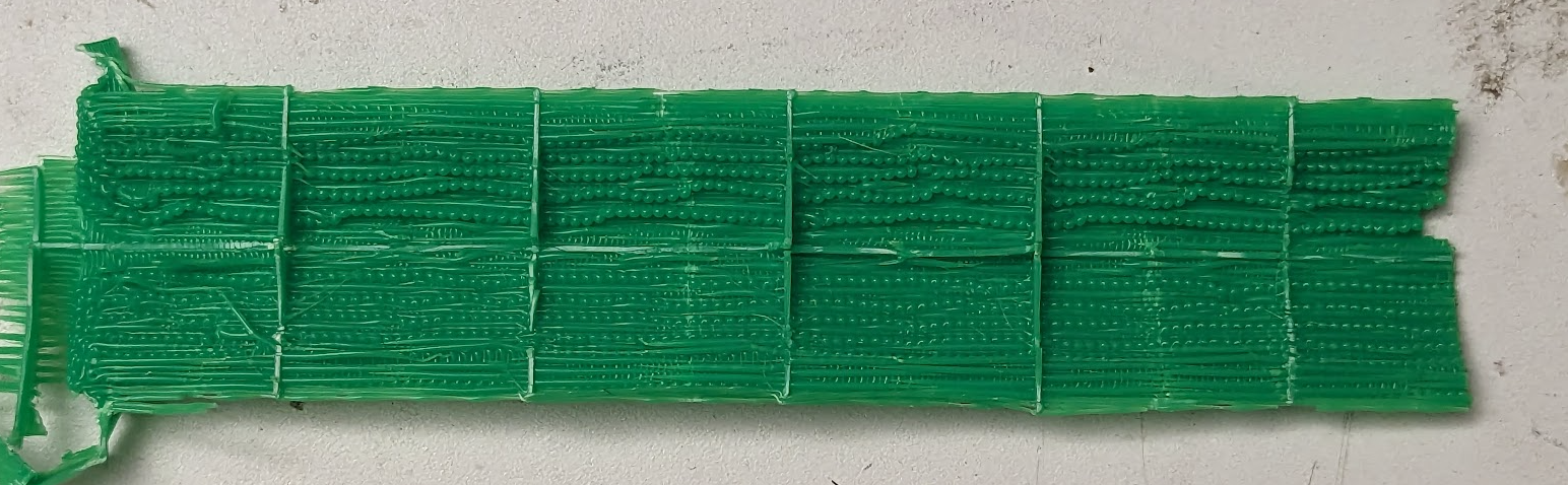
After printing, the results look like this:
Much better! when I attached the arm to the base and flexed it to failure it failed via buckling. I actually think I went too far with the reinforcement and need to back it off. The bucking failure occurred I think because this section of the bottom of the arm:
Never actually attached to the wall (which I confirmed in the slicer) and so when it went under compression the bottom tape bit buckled early as it wasn’t attached.
At this point I think that I have things down pretty well and I can do a run of prints and assemble the drone again for flying.
Overall I don’t think that I’ve done that well though - The arm is still like 2g heavier than the one printed with the cura slicer (with 0.2mm nozzle size). The middle is about the same weight, but the cura one was not very well optimised I think. The arms do seem quite a lot stronger though.
I might try printing arms with the 0.2mm nozzle that I bought in a while, but unless you buy the bambu complete hot end assembly thing changing the nozzle is a massive pain as you have to thermal paste the new heater + thermistor on etc.
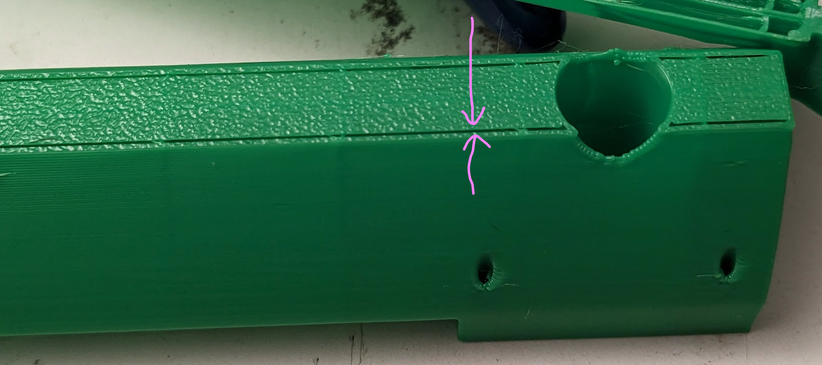
One other thing I think I can do is change the cross section of the arm to a vertical ellipse. This will reduce drag from the propellers, reduce material because the cross section is smaller but then also reduce it because the top of the arm won’t be flat and as such won’t have a big strip of material like this:
which is clearly a very inefficient use of filament. I should be able to save 1-2g of material per arm here I think.