Trying to build a plasma toroid following this guide:
https://docs.google.com/document/d/1AyaO-RaTiaOmyT3-89UxPdrMHEBCCrxb1irZKsVMg_8/edit https://docs.google.com/document/d/1-jMPQOSs6-Flp181TTa8cNMSs2XumzDEahg9DVD0hKk/edit
Here is the circuit in LT spice:
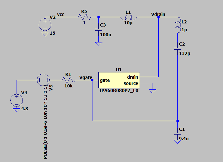
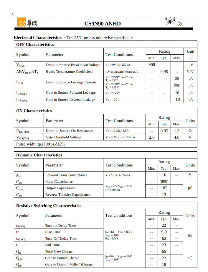
My transistor is a CS9N90 (lcsc special):
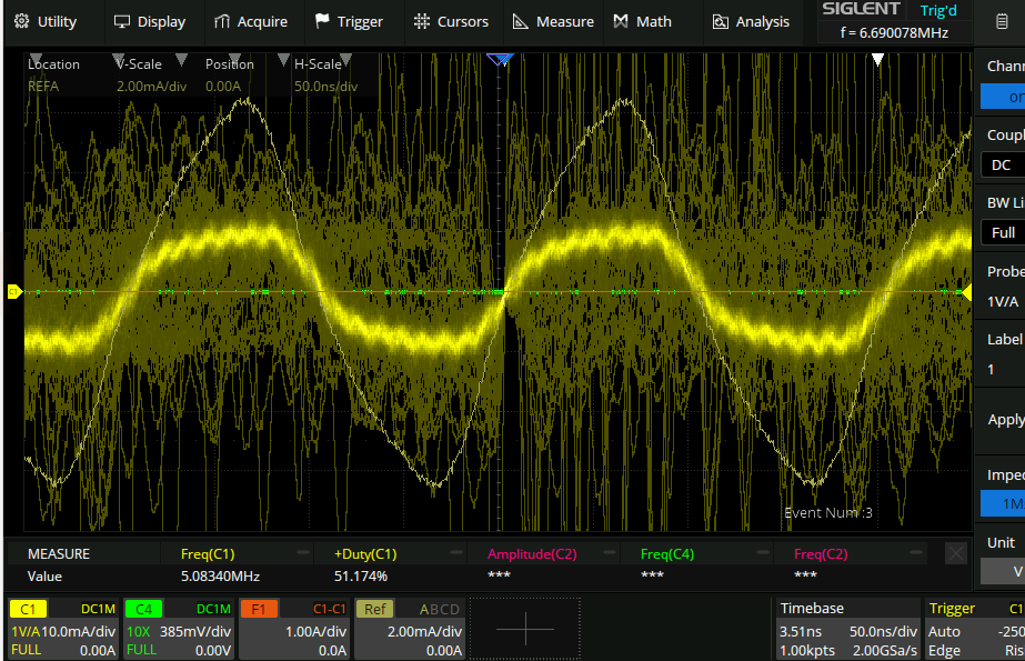
My capacitors are only rated to 50V, and so I get a squealing noise, but the circuit does oscillate:
I wonder why it only oscillates for a while… possibly it is the high voltage on the caps (150V!) that causes them to be lower in capacitance and stop the oscillation.
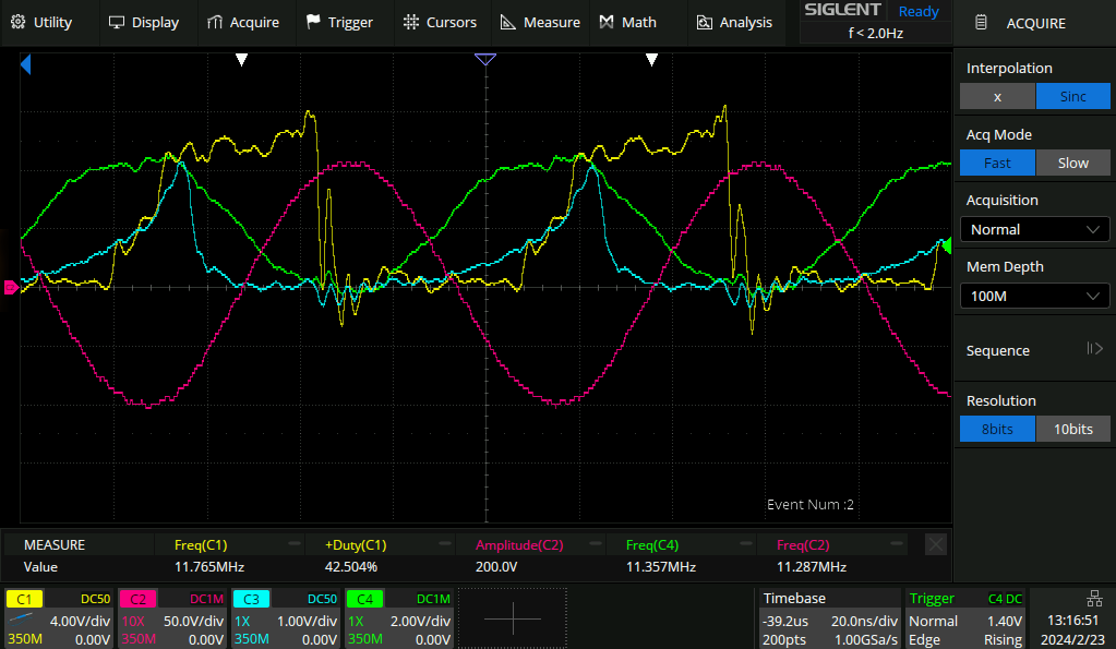
After making a bunch of adjustments and the squealing noise mysteriously disappearing the oscillator seems to work fine:
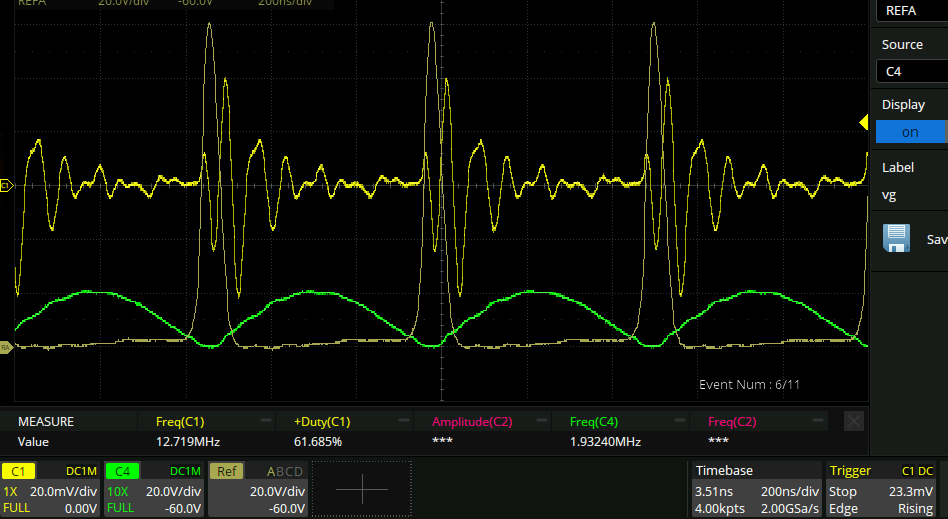
 Here I have changed the probing though - it seems that just using a divider does not work very well in this situation for some reason.
- Yellow is the drain of the FET, probed with the clippy bit of a scope probe.
- Blue is the gate of the FET probed with the clippy bit attached to a 3cm piece of wire hanging off the gate.
- Green is the gate of the FET probed using a springen sproingen - clearly way better signal integrity. If this oscillator is going to work as it should then there needs to be zero voltage switching of the FET and so good measurements of the drain and the gate are necessary. So I need to make some high voltage probes.
500R transmission line
I just learned that the way that 10x oscilloscope probes work is that they have a special lossy transmission line inside them to do the impedance matching between the 9M probe tip and the 1M scope input.
Here is a video on the topic: https://www.youtube.com/watch?v=OiAmER1OJh4
If one could make a 10kR transmission line though, you could have a 10k resistance at the scope and a 1M resistance at the probe tip, and then everything would be all matched and work fine.
Looking at the impedance calculator website here, it seems that a 500R transmission line is easily achievable (0.22mm diameter wire wrapped about 5mm diameter insulator) but that going higher is very difficult, on acccount of the log here:
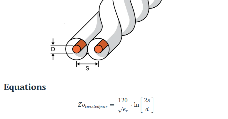
The test setup is to run a square wave out of the signal generator and terminate it at a pcb with a 50R resistor. From there a 500R resistor takes it into the 500R twisted pair line, and a 500R terminating resistor at the scope (with its 1M input impedance).
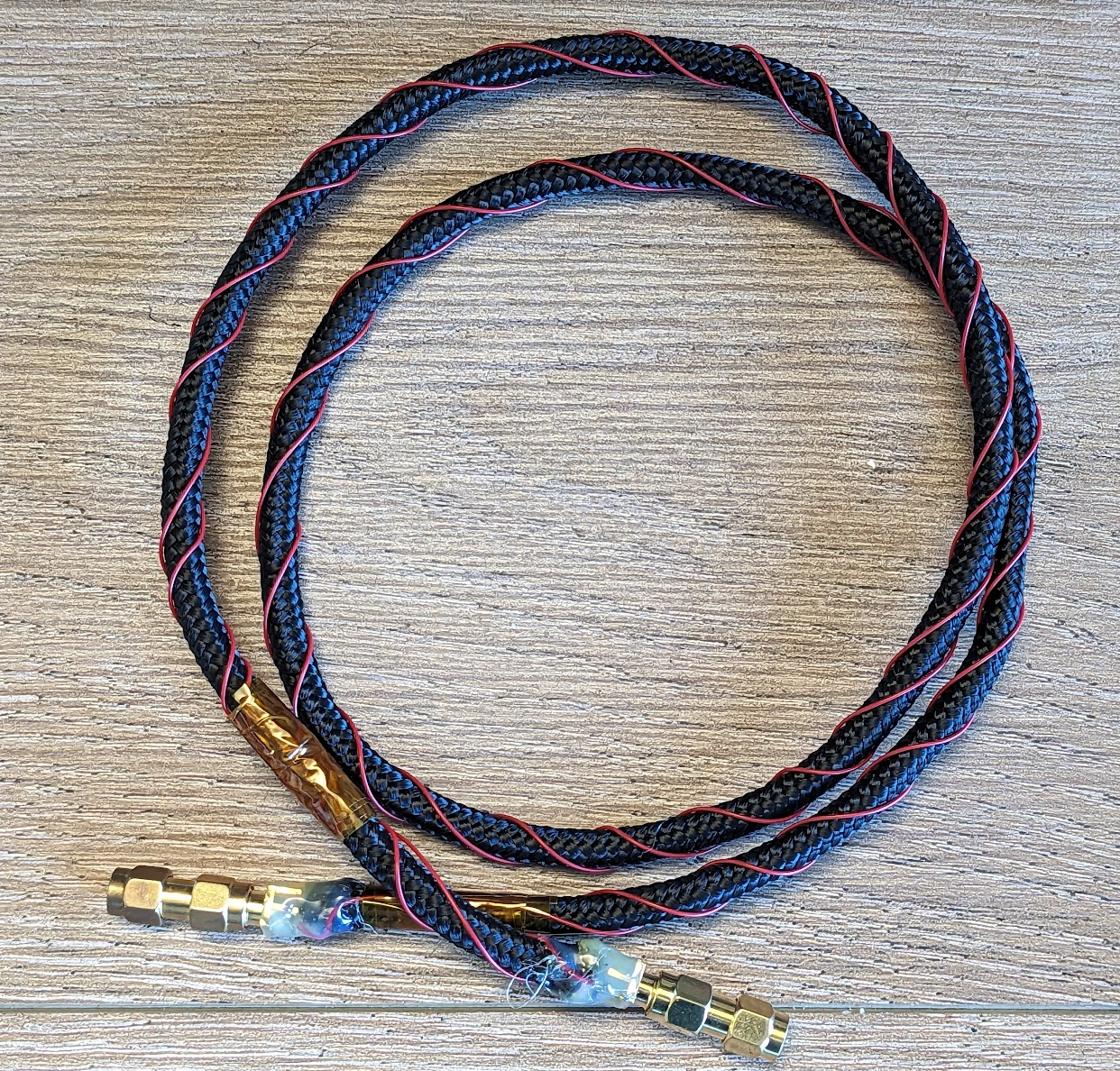
Here is what it looks like all wound up:
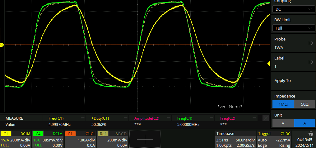
Here the reference trace is the 500R line, the green trace is the 50R resistor probed with a normal 10x probe, and the yellow is a standard 50R coax line. I was hoping to see some reflections off the coax line, but I guess not :(
Changing the probing resistor to 50kR gives this:
…There seems to be too much noise pickup for anything useful. When I turn on the toroid oscillator it’s totally unusable.
Back to the circuit
I went to Home depot and bought a circular fluorescent bulb. The bulb lit up! Then I took apart the circuit and put it back together again. It looks like it is performing much better now:
- Ref: drain (the nice pulse)
- Green: gate of the FET
- yellow: some resistor sticking out of one channel of the scope that I am using to trigger. So I am getting pulses at 120V! But now the fluorescent bulb no longer lights up :(. The big rf coil is next to a large aluminium heatsink though, I wonder if it is somehow reacting with that and losing energy.
Zero voltage switching (ZVS) simulation
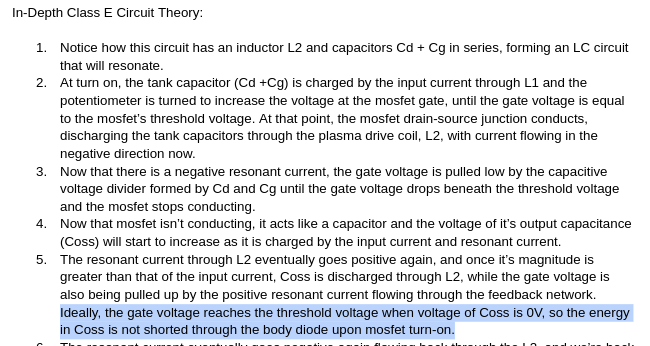
I found another good document about the operation of ZVS. Here is what is has to say on the topic of ZVS:
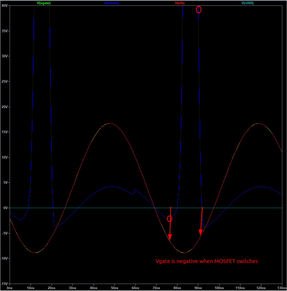
And here is the operation of the circuit in LT spice:
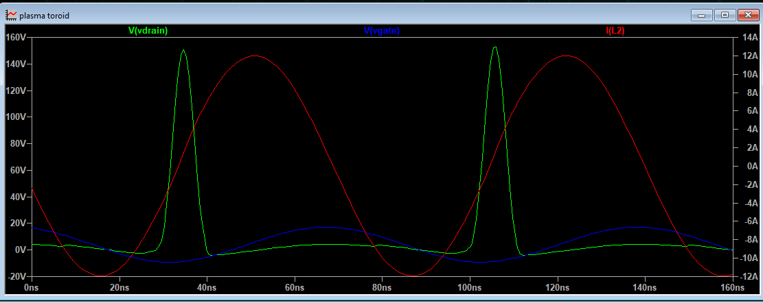
What I do not understand here is when the MOSFET goes open. It clearly happens when the gate voltage is just starting to rise up to around 0. But is this because of ZVS, or because that’s just how MOSFET’s work so of course that happened/
puzzling observation 1
circuit at the time of the above screenshot;

New circuit
I made a new circuit that looks like this:
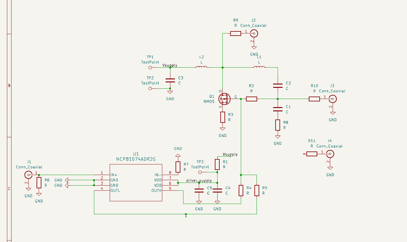
where the FET can be driven open loop - the feedback path is closed. That way hopefully we can observe what the actual resonant frequencies are and check that ZVS is a thing.
The drain at open loop.
Probing the drain of the FET looks like this:
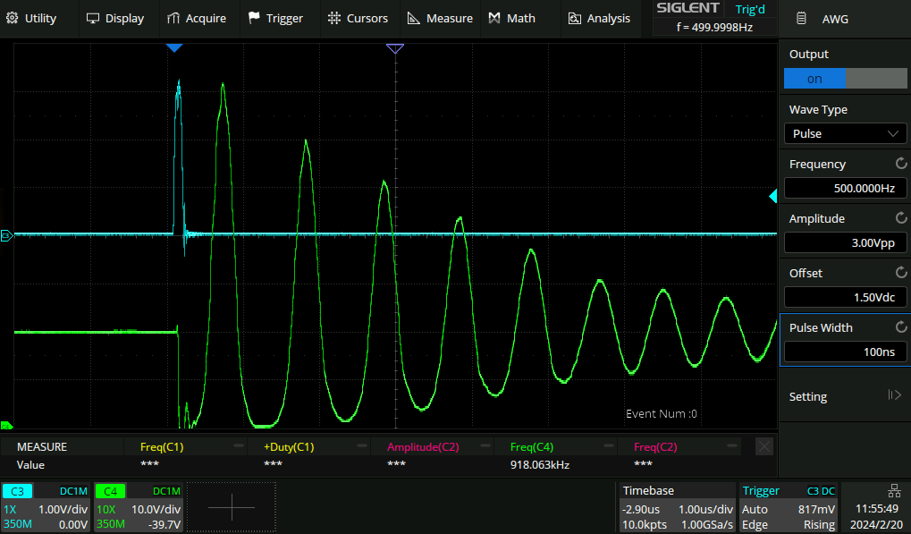
Which is 1MHz - far below the supposed 10MHz of the tank circuit!
Impedance
Here is the impedance of the big coil and the 130p cap tank circuit:
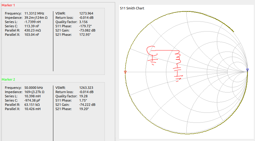
which looks absolutely perfect - 0 resistance at 11Mhz. Since the tank circuit is disconnected from the main circuit I took the liberty of probing the drain of the FET without the tank circuit attached and got the exact same measurement - so I guess what is happening here is the input choke is forming a tank with the FET capacitance.
Voltage in the middle of the tank circuit
Here I have added the main inductor and capacitor back in, and am probing in between the inductor and capacitor:
 That looks much more correct.
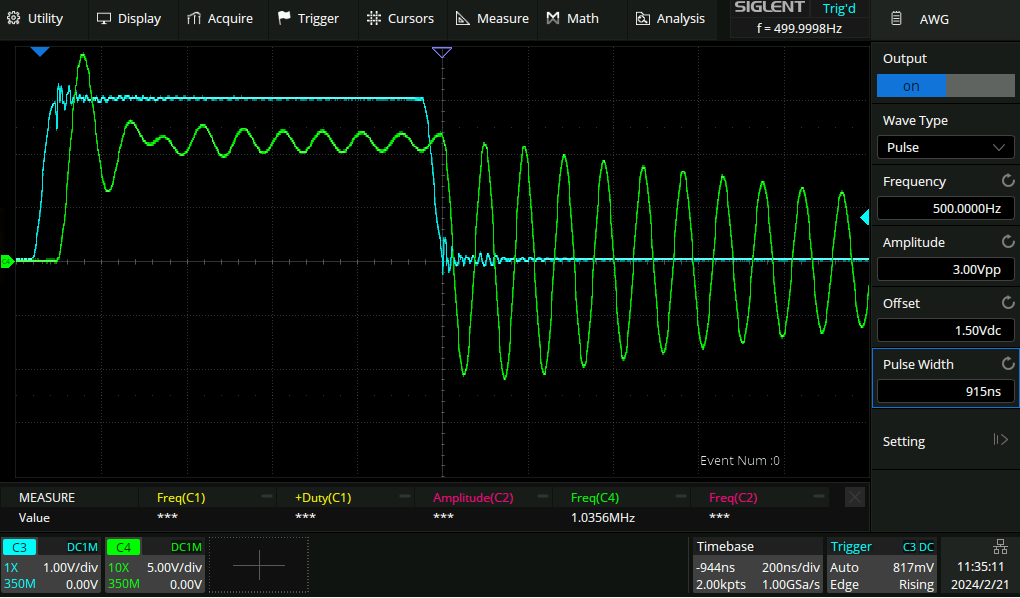
Pulse train
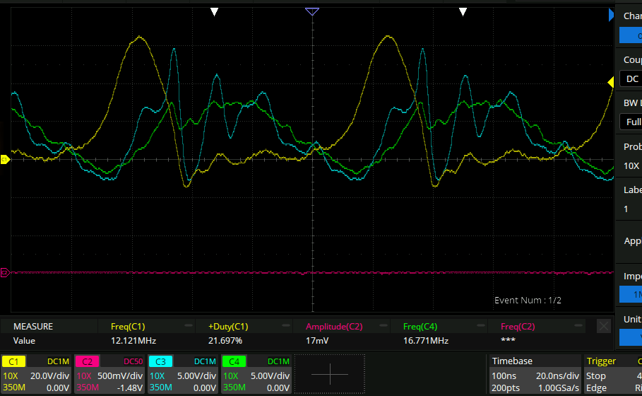
It turns out if you drive the MOSFET driver at 10MHz with this kind of load it burns out after a few 10s of seconds. So I set up the signal generator to generate a pulse train. Here I have tried pulse trains of frequency 10, 11, 12MHz around the resonant frequency of 11.3MHz.
So we can see here that being close to resonance is important. how utterly unsurprising.
Longer turn-on
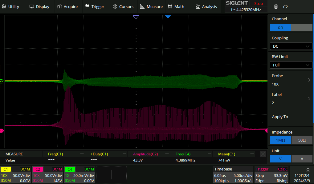
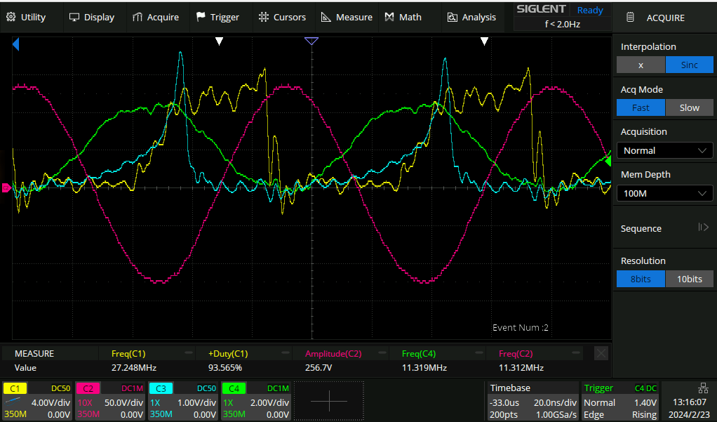
Here I replaced the FET with a IPA60R080P, which has about half the input capacitance. that makes the waveform at the gate look somewhat sensible. Here is a 1000 cycle turnon transient at 11.3MHz:
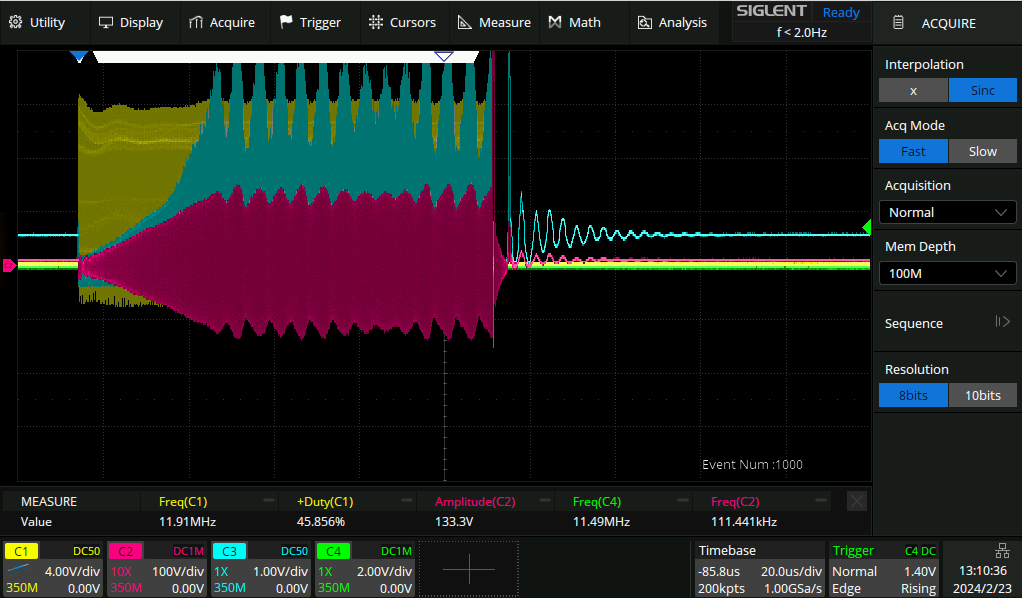
- Yellow: gate waveform
- Green: AWG
- Cyan: drain
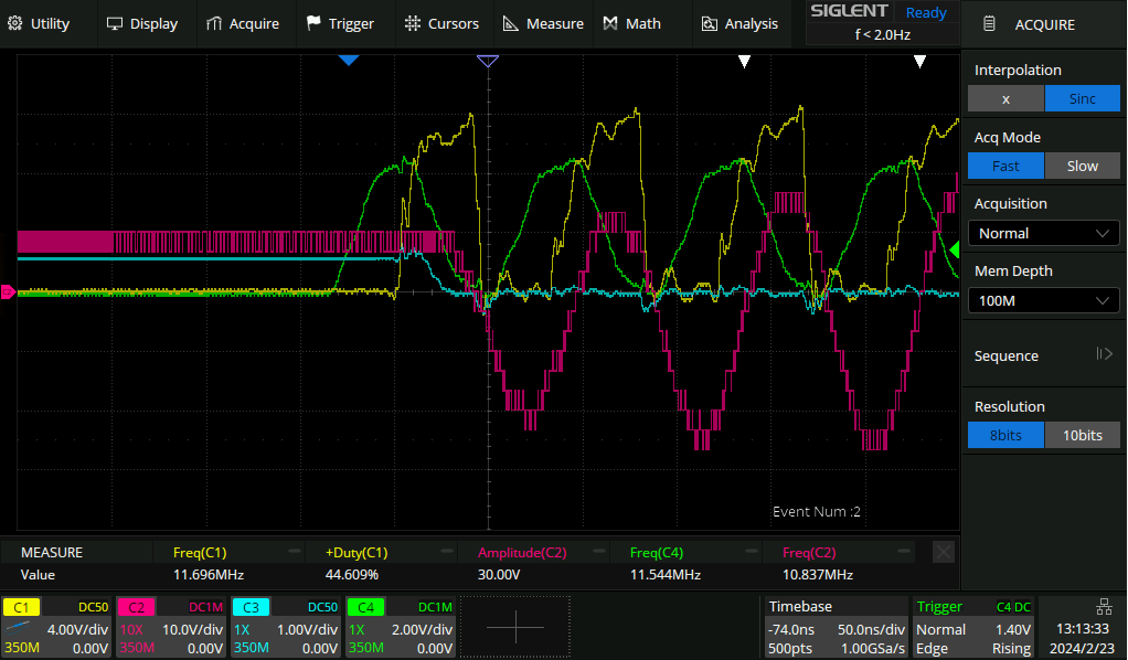
- purple: between inductor and capacitor. The oscillations in the maximum amplitude of the drain and the resonance circuit are real, and I think that might be some oscillating phase shifts as it gets closer and further away from ZVS. Let’s zoom in:
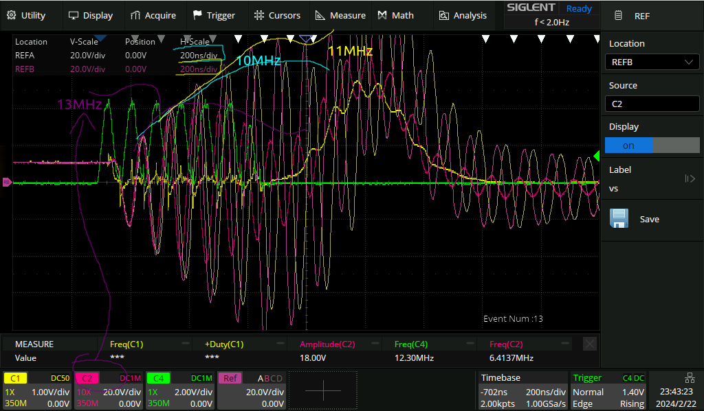
Beginning of the turn-on
The phase shifts look like this:
So you can see there is about a 25ns delay between when the gate driver goes high (yellow) and when the drain goes low, and a 50ns delay between when the driver goes high and the voltage at the cap starts to drop.
High drain voltage:
Low drain voltage