Instead of having a class whatever oscillator with zero voltage switching nonsense to not blow up the FET, how about a simple push pull half bridge to drive the LC oscillator directly:
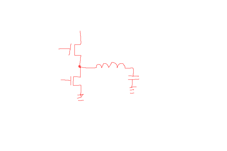
Something a little like this:
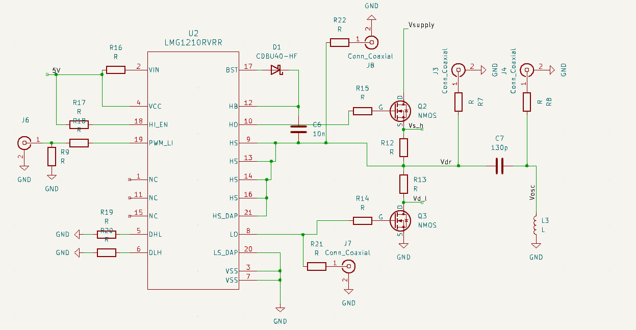
The only trouble I had with this was finding a gate driver that claimed to be able to switch fast enough. previously the FET driver would smoke out after a few seconds of operation.
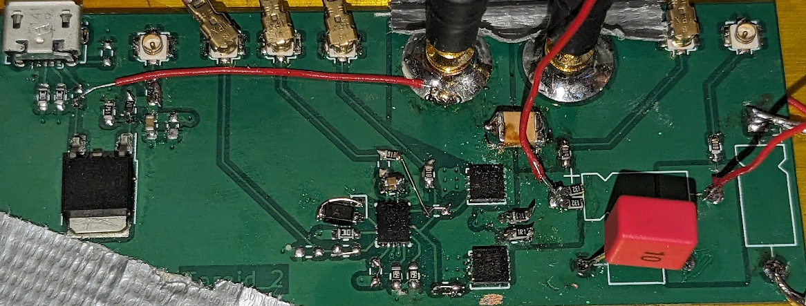
The PCB looks like this:
Anyway, after lowing up the FET driver once and resoldering, I get this:
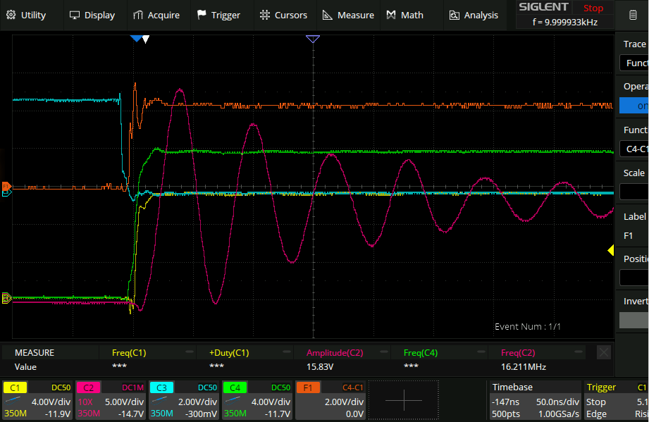
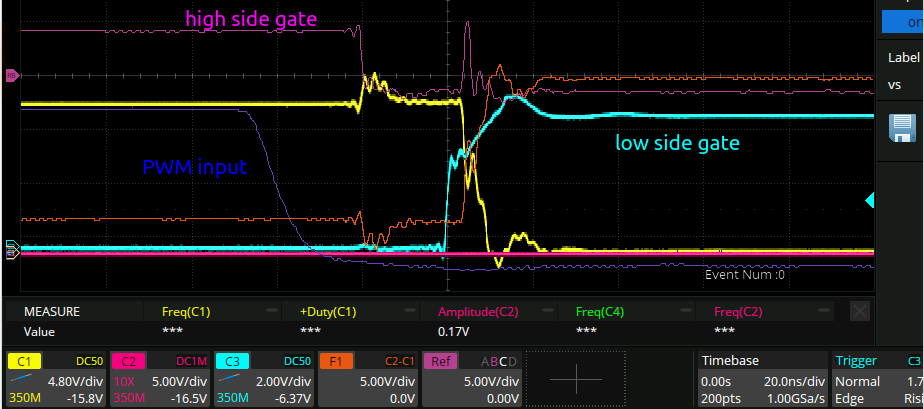
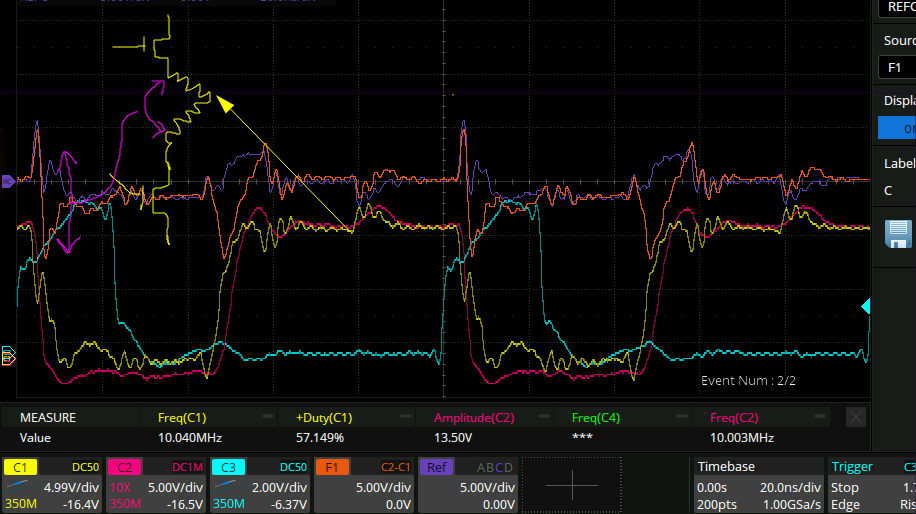
Green is high side FET gate, cyan is low side FET gate, yellow is middle of the half bridge, maths is top FET gate - middle of half bridge (so the gate-source voltage of the top FET). And finally purple is after the inductor. So now all that needs to be done is crank up the frequency to the frequency of the purple oscillations, and bam! plasma toroid.
*Pop*
aaand it died. once I changed the resistors r12 and R13 that limited the current from power to ground, it worked for a little bit and then died, killing the top FET and the LMG1210. I resoldered new ones on and replaced the resistors with 1.4R resistors, which will hopefully act like fuses. I also changed the bootstrap cap:
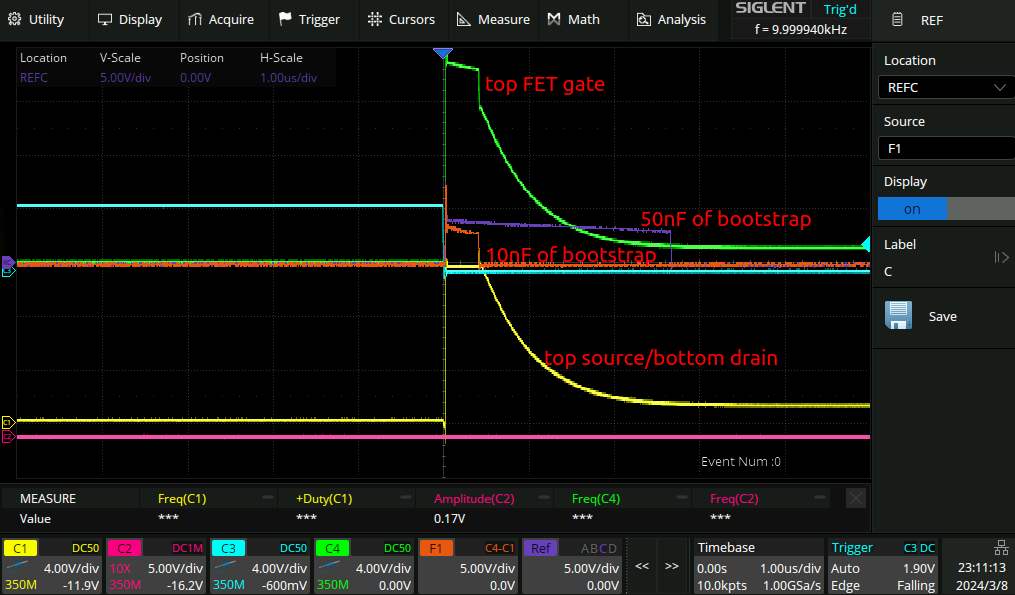
I calculated that I needed 10nF from the datasheet, but it looks like even 50nF is not even close to enough. I wonder why the voltage on the gate of the FET is decaying over time? I desoldered the connection to the gate ofthe FET and measured the resistance to the source, it is open circuit as you would expect.
After changing the bootstrap cap to 1uF I get this waveform:
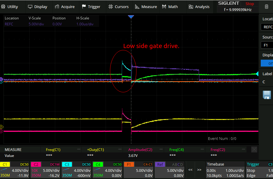
…The low side drive changed to only be 1us long?!??! Time to go read the datasheet…
…
…
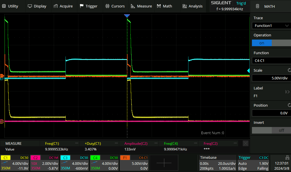
The reason why the gate voltage was decaying over time was that I had a 1kR resistor with a 50R resistor as a probe to ground so I could scope the voltage on the gate.
Higher frequency.
Now things work fine. But after cranking the frequency of the AWG up from 10kHz to 560kHz the top side FET stops being driven halfway through the cycle:
This time the voltage on the gate is clearly not decaying over time, so it’s really not clear what the source of the issue is.
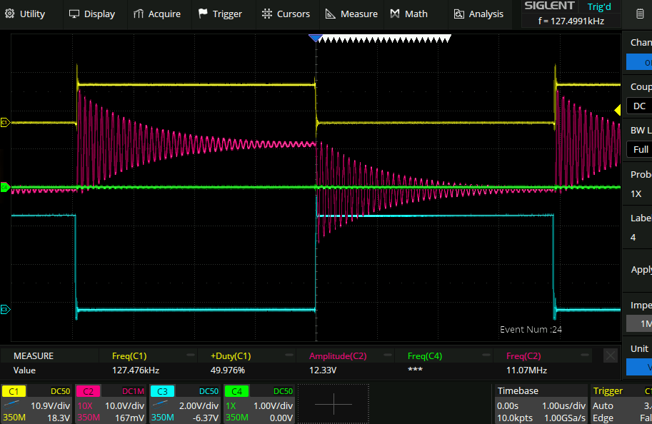
I set up the waveform generator for a 1MHz burst with 35 cycles:
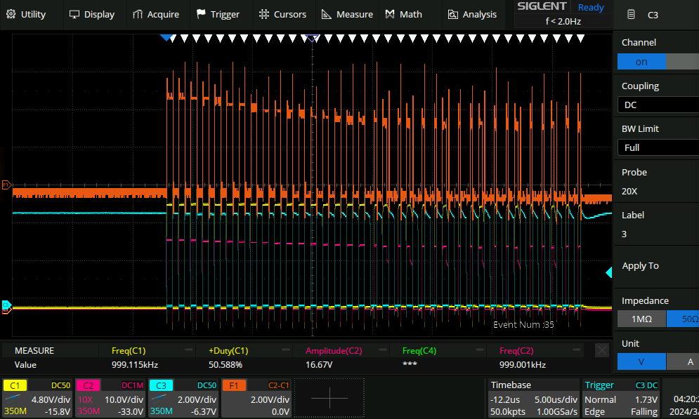
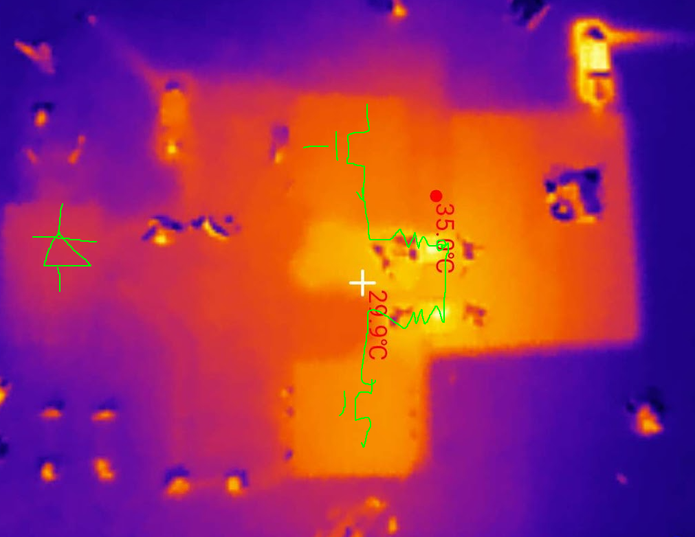
So clearly it actually is the gate voltage that is sagging here. I noticed also on the thermal camera that the bootstrap diode was getting a workout in:
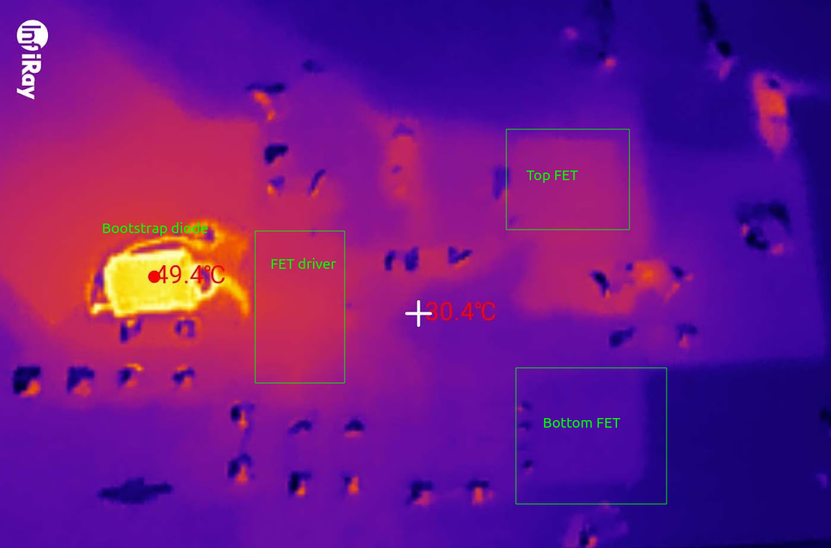
so this might have something to do with it. Back to the datasheet!

The reverse recovery time of my diode from the pantry (SM4001PL):

hmmm… I have no other diodes though. I do have a BFR106, a 20GHz NPN transistor. wiring it as a diode does not seem to work well though. Weird considering this rather good post would suggest that transistors don’t have much of a reverse recovery time. I do have some buck converters though, and they do have shottkey diodes in them:
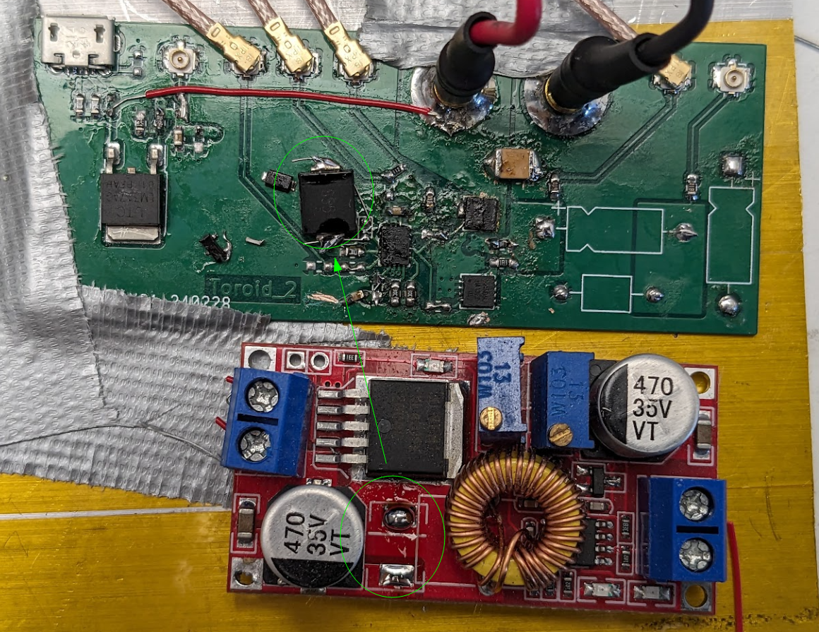
Bam! continuous operation at 1MHz, no problem.
The resistors seem to be heating up a tad though:
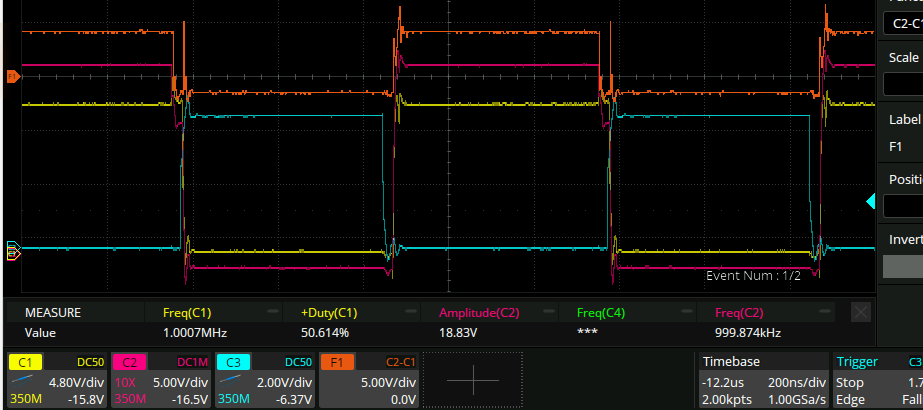
I want to be reallly sure that everything is working well and there is not shoot through or anything on the circuit.
The falling edge seems fine, but on the rising edge here there looks like there is negative dead time:
20ns is the same as what the datasheet says the maximum dead time is. suspicious.
…actually I have things wrong, this looks fine. Although it doesn’t quite look like what the datasheet has:
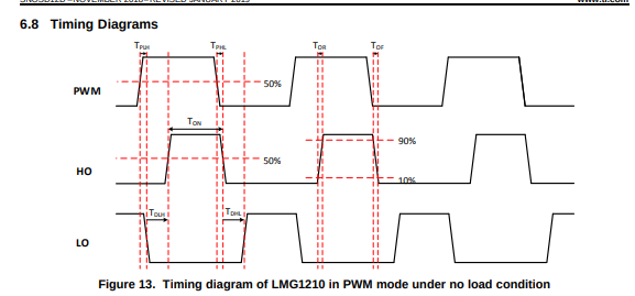 …actually though it looks like Tphl is about the same as TdHl. Diagram should have a “not to scale!“.
Cranking things all the way up to 11MHz we get this:
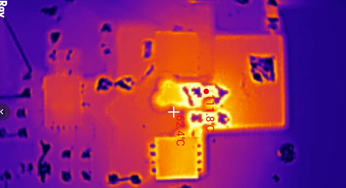
so the resistors are at 120C. I paid for the whole thermal range and I’m gonna use it. The bottom FET is at 60C though which is worrying. we aren’t even switching any load yet.
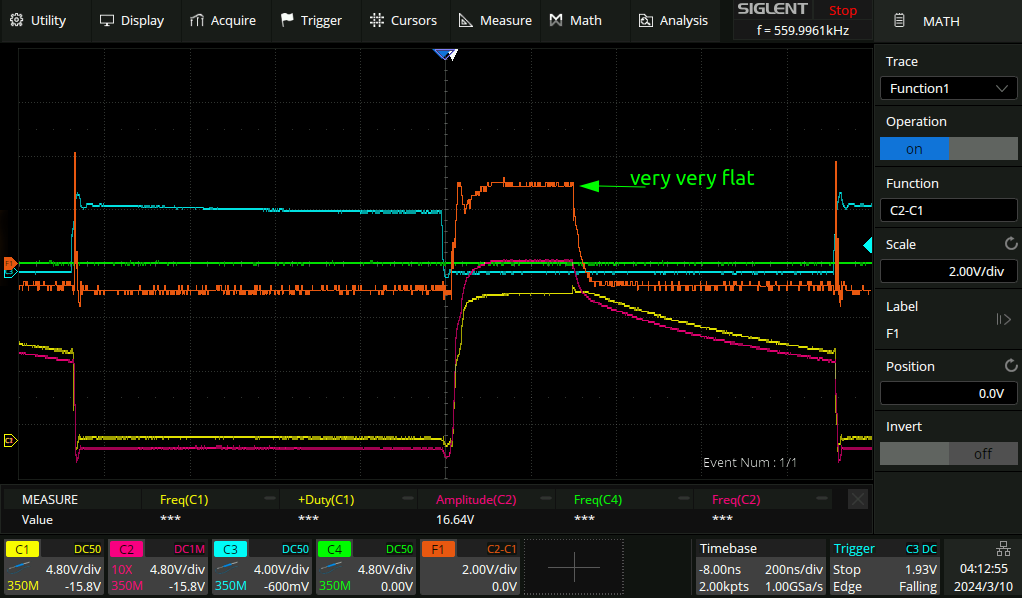
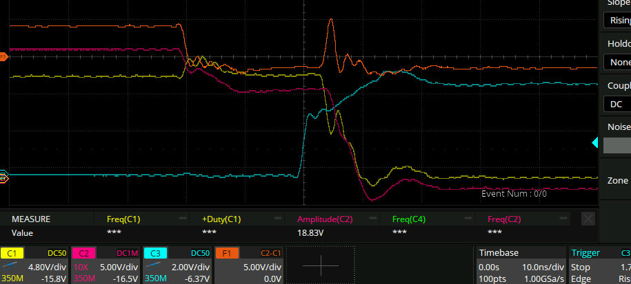
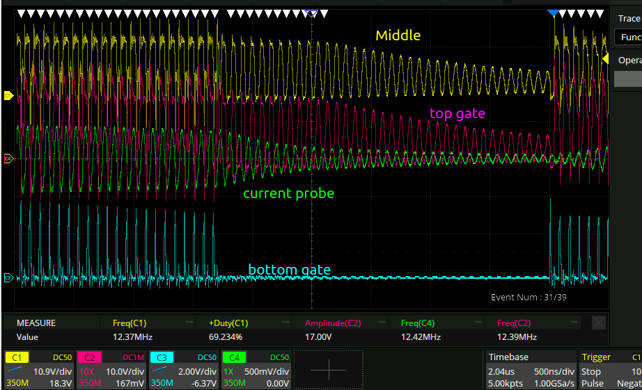
Since there are actual resistors that are drawing actual current, we can probe across them to get an idea of when exactly the current is being drawn to see if it is an an appropriate time etc:
This is a bit complicated but you can see from the difference between the purple and orange traces that there is clearly current flowing on the rising and falling edges of the middle of the two FET’s. That’s just the expected transient time when the MOSFET is in an intermediary state I guess, not much can be done other than to switch to a GANFET or something.
Previously the board was just floating in the air. I taped it down to a chunk of aluminium with some thermal paste in the middle, that reduced the temperature of the FET’s to 40C. the circuit is already drawing 380mA/5W though. If the mosfets heat up by 20C from drawing 5W, that does not bode well for putting 60W into them. So I reduced the power rail from 12 to 7V going forward, hopefully that will limit the current draw a bunch when attached to the actual coil.
coax dielectric
The 0603 100pF capacitors were getting really hot, as were the film caps. So I got 100pF worth of coax cable and added it on instead. It still got a bit warm though, so I don’t know that overall it was a huge improvement in terms of increasing the Q of the circuit. It mostly just spread out the heat dissipation I think.
108pF worth:
Failure under high load /?
Under conditions right next to optimal tuning the circuit starts to turn on/off intermittently like this:
it’s not 100% related to frequency or anything, I don’t really know what the root cause is. But I notice that the lower gate drive pulse is quite narrow.
Zooming in and doing maths gets this:
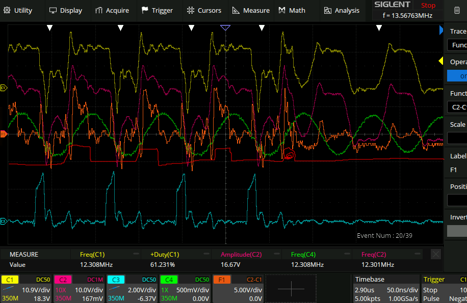
That’s my interpretation of the high side gate drive. I think what needs to be done now perhaps is to reduce the dead times.
I added a 100k pot in series with the 20k resistor that sets the dead time and swept it back and forth. whilst it did adjust the dead time, it did not seem to make a difference with the above short pulse. Changing the duty cycle of the awg from 50% to 40% did seem to do something though, and after a bit more twiddling I burnt the sma connecter right off the board:
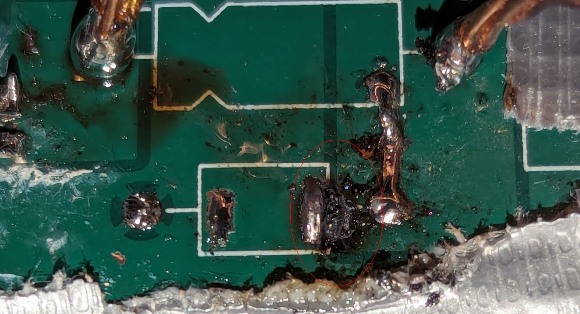
oh well.