ostensible read pattern:
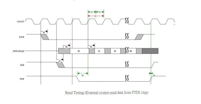
Taken from here.
Here is what I observe:
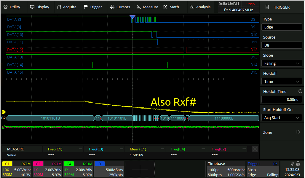
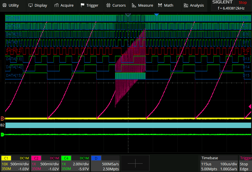
above logic analyzer signals are in the same order as the official ftdi screenshot. Looks like rxf# is going low rather slowly.
..This turned out not to be the issue. the issue was just that I wasn’t putting the ft232h into the right sync fifo mode.
Working, effect of coax loading
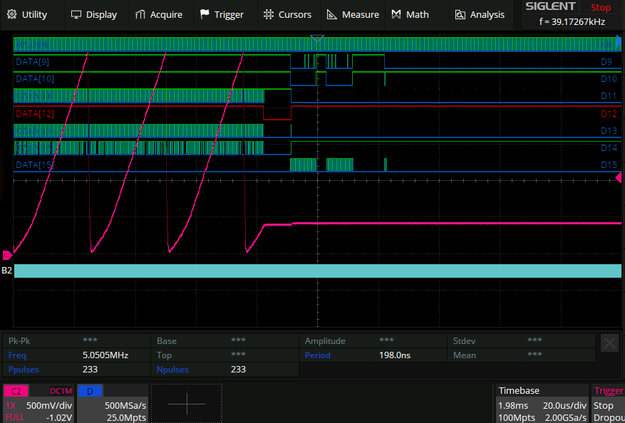
Here is the r2r dac working properly finally. I have a ramp, the falling edge of which can be seen here:
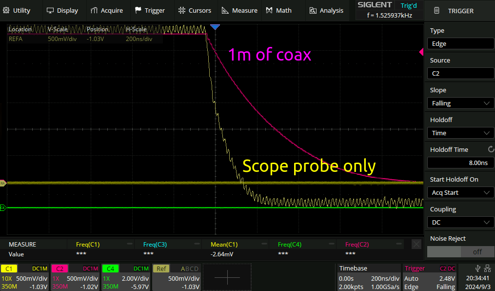
This is with 1kR resistors. So to meet the 10MHz spec they would need to be 1/2 of what they are to go from 200ns fall time to 100ns.
State machine tribulations
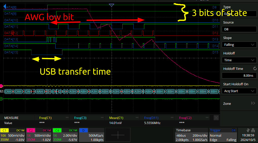
The logic bus is defined as follows:
    always @(posedge clk100) begin
        logic_out[2:0] <= state_dbg;
        logic_out[3] <= data_cnt_dbg[0];
        logic_out[4] <= awg_valid;
        logic_out[5] <= fsm_tvalid;
        logic_out[6] <= fsm_tready;
        logic_out[7] <= fsm_tdata[7];
    end
Here is the state machine after the first packet sent from the PC to the AWG:
And a bunch of packets after that: (~10)
The definitions of the state machine are here:
    // State machine parameters
    localparam [2:0] S_IDLE       = 3'b010,
                     S_SET_LENGTH = 3'b001,
                     S_TRANSFER   = 3'b011,
                     S_COOLDOWN   = 3'b101;
    reg [2:0] state = S_IDLE;
    assign state_dbg = state;
So you can see it starts off in S_IDLE which is correct, but ends up in S_TRANSFER, which is wrong, it should be back to S_IDLE. Here is the transfer that happened just before the bad one:
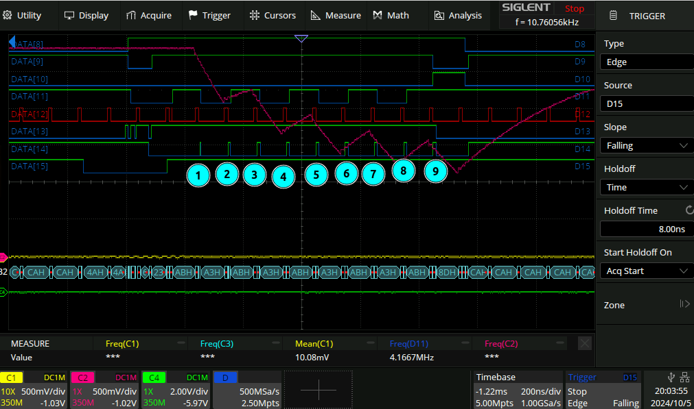
This one has 9 pulses on the fsm_tready line not the normal 8!
Next day
I sent out some PCB’s which will hopefully allow me to use the full 16 bits of the digital inputs of my scope rather than the current manually-soldered-two-ethernet-cables 8.
Next couple of days
I went and discussed the above protocol where [header byte], [length], [waveform data] was sent and apparently this is a bad way to do things because if you pop a cog somewhere you start interpreting waveform data as a header/length, and then you are completely lost. I agree with this take. Instead, you should reserve a bit or a magic value in the stream such that the state of the fpga can be reset at any time. Here is a diagram claude made for me to describe the reserved bit version of the system:
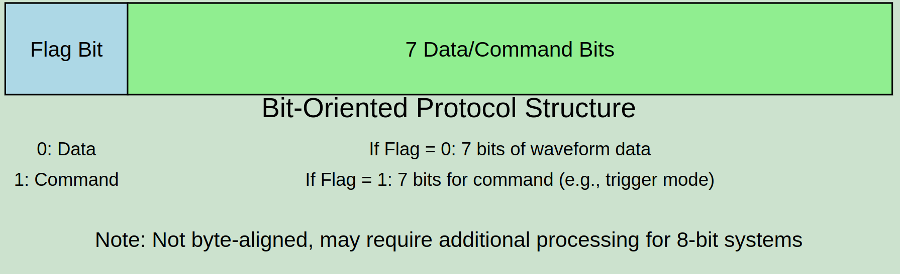
I implemented this and indeed it seems at first glance to be much better. Here is a sin wave sent out:
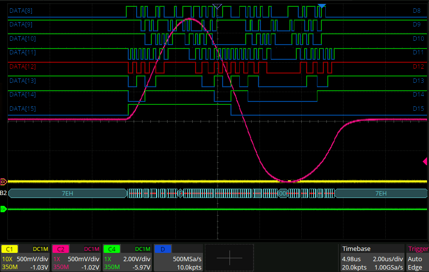
The horrible nonlinearities in the sin wave are just the R2R DAC. you can see from the digital stream that it’s working! So that’s nice. The stream does have a tendency to lock up sometimes though, so I need to figure that out.
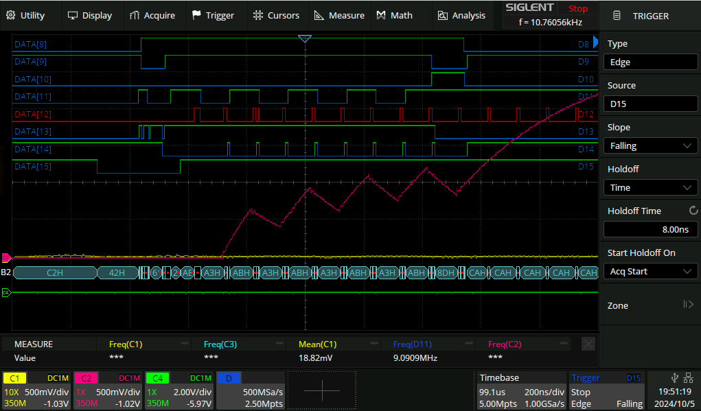
Bit untwiddling
It also has this bug, whereby when I send a message that’s large enough that the ftdi chip needs to do flow control, I get something that looks like this sometimes:
Which looks like a bit got flipped somewhere. That is one problem though. The more eggregious one is where the whole state machine locks up somehow and doesn’t let any more data in:
The data definitions are as follows:
   always @(ftdi_clk) begin
        logic_out[0] <= ftdi_clk;
        logic_out[1] <= ftdi_rxf_n;
        logic_out[2] <= ftdi_oe_n;
        logic_out[3] <= ftdi_fsm_ready;
        logic_out[4] <= ftdi_fsm_valid;
        logic_out[5] <= awg_valid;
        logic_out[6] <= ftdi_fsm_data[0];
        logic_out[7] <= ftdi_data[0];
    end
From the ftdi datasheet about the way that data flows through the ftdi chip for a read operation:
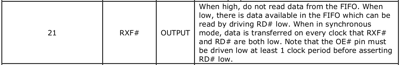
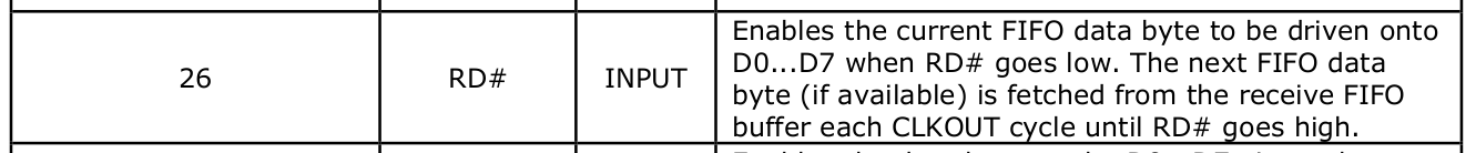
So we can see from bits 1 and 2 that the ftdi is signalling via rxf that there is data available, and from bit 2 oe that we are not requesting any data. That goes into the third party fifo and then data from that fifo is signalled as being ready by ftdi_fsm_ready (because the data is flowing from the ftdi chip into my finite state machine).
That in turn says there is data available. But ftdi_fsm_valid goes low for a good long while during which the awg output is flat. It goes high again after that and some stuff happens but I think that’s the chook running around with its head off at that point.
Here is the entirety of the “state machine”:
module state_machine (
    input  wire         clk100,

    input  wire         in_tvalid,
    output reg          in_tready = 1,
    input  wire  [7:0]  in_tdata,

    output reg         awg_valid = 0,
    input wire         awg_ready,
    output reg [7:0]   awg_out,

    output reg [6:0] trigger_mode,

    // Debugging:
    output wire [2:0] state_dbg,
    output wire [31:0] data_cnt_dbg
);

    assign data_cnt_dbg[7:0] = in_tdata;

    wire cmd_bit = in_tdata[7]; // Debugging
    wire [6:0] wire_payload = in_tdata[6:0]; // Debugging

    reg [7:0] new_bits_in_sample = 0;
    reg [7:0] awg_partial_lhs = 0;
    reg [7:0] awg_partial_rhs = 0;
    reg [7:0] awg_partial = 0;
    reg [7:0] bits_in_sample = 0;
    reg [7:0] awg_next = 0;
    // reg awg_valid = 0;
    reg [8*22-1:0] state_name; // Debugging

    // wire [7:0] bits_left_in_sample = 8 - bits_in_sample;
    always @(posedge clk100) begin

        if (awg_ready && awg_valid) begin
            awg_out <= awg_next;
            awg_valid <= 0;
            in_tready <= 1;
        end

        if (in_tvalid) begin
            if (in_tdata[7] == 1) begin // Command
                if (wire_payload == `TRIGGER_MODE_NONE || wire_payload == `TRIGGER_MODE_EDGE) begin
                    trigger_mode <= wire_payload;
                    state_name <= "CMD_TRIG";
                end else if (wire_payload == `RESET_TRANSMISSION) begin
                    state_name <= "CMD_RST";
                    bits_in_sample <= 0;
                    awg_partial <= 0;
                    // We do not invalidate awg_next here as that command has already been issued,
                    // so that would represent a command reaching back in time.
                end else begin
                    state_name <= "CMD_ERR";
                    $display("Unknown trigger mode: %b", wire_payload);
                end

                in_tready <= ~awg_valid;

            end else begin

                if (bits_in_sample + 7 >= 8) begin

                    if (in_tready) begin
                        state_name <= "REMAINDER_ASSIGN";
                        awg_next <= awg_partial | (in_tdata >> (bits_in_sample - 1));
                        new_bits_in_sample = (bits_in_sample + 7) % 8;
                        awg_partial_lhs = (awg_partial << bits_in_sample)    & (8'hFF << new_bits_in_sample);
                        awg_partial_rhs = (in_tdata << (8 - new_bits_in_sample));
                        awg_partial <= awg_partial_lhs | awg_partial_rhs;
                        bits_in_sample <= new_bits_in_sample;

                        awg_valid <= 1;
                        in_tready <= 0;
                    end else begin
                        state_name <= "REMAINDER_WAiT";
                    end


                end else begin
                    if (in_tready) begin
                        state_name <= "NO_REMAINDER";
                        awg_partial <= in_tdata << 1;
                        bits_in_sample <= bits_in_sample + 7;
                        in_tready <= ~awg_valid;
                    end else begin
                        state_name <= "~NO_REMAINDER";
                        in_tready <= 1;
                    end
                    // TODO: sim assert that bits in sample is 0 here.
                end
            end
        end else begin
            state_name <= "IN_INVALID";
        end

    end

endmodule