The waveform generator now seems to do more or less the right thing. I send it samples, it outputs those samples. It doesn’t glitch or hang. I didn’t fix the glitchy bug on purpose though so gotta keep an eye out for recurrences of that.
Interrupt latency.
I have noticed sometimes the data stream is interrupted for a few hundred us to a ms or so, and it seems that the cause for this is just the PC not sending data in time. So I think beefing up the FIFO size is in order. But here is a profile of 1e6 data transmits of 257 bytes each:
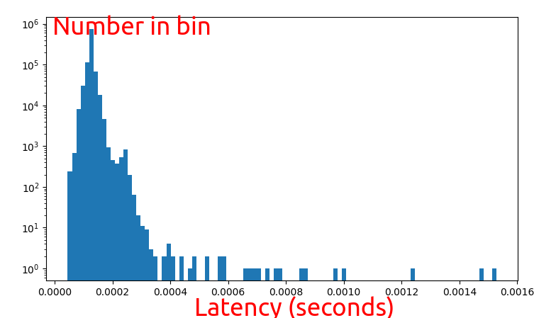
Looks like it tops out at only a millisecond or so. The FIFO currently is 14 bits wide. Each byte of transmit data only contains 7 bits of waveform data and I’m transmitting 10MSa/s of waveform data. So that’s (1 << 14) * (7/8) / 10e6 = 1.4ms I should probably bump that up!
But when I do that the fpga tool says:
Info: Placed 34 cells based on constraints.
ERROR: Unable to place cell 'u_ftdi_245fifo_top.u_rx_fifo_async.buffer.0.53', no BELs remaining to implement cell type 'DP16KD'
0 warnings, 1 error
make: *** [Makefile:49: fpga_top_ft232h_loopback_out.config] Error 255
So I think I need to finally figure out how to use these blockram thingos.
Looking around in the docs though it seems that I am already using them. Oh well that’s all I get. I also discovered too that timing doesn’t close if I use as many as I can. That is an actual problem, as I need all that buffer to not have dropouts.
Triggered
I finally got the waveform system working. Spent quite a while trying to make a truly combinatorial/unclocked triggering block but yosys just wasn’t having it, so it is clocked for now. Here is an image of the waveform being triggered:
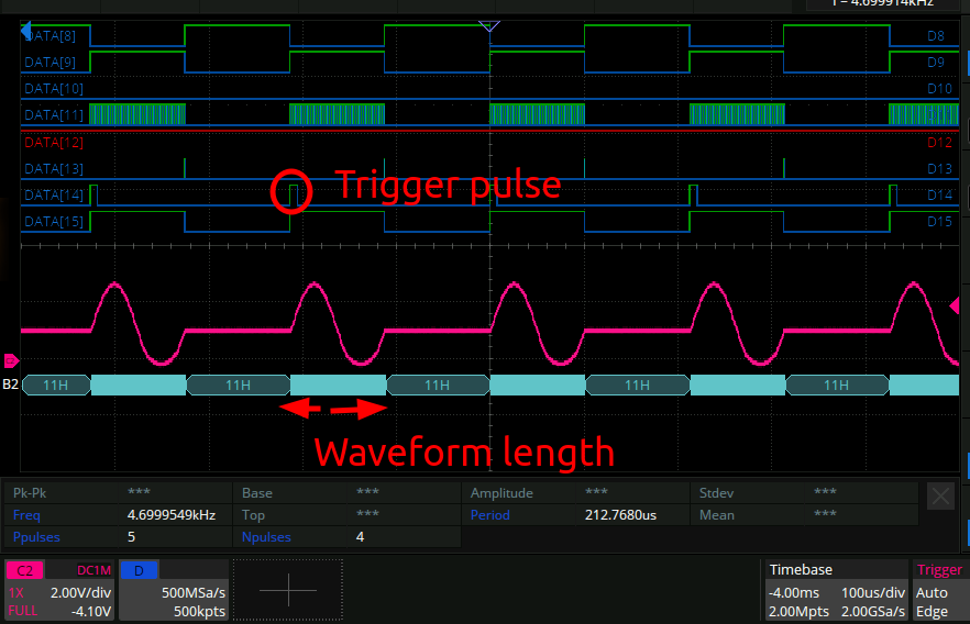
Wondrous.
However, there are still bugs. Currently it seems that the signal cannot be triggered rapidly. Also, sometimes the system ends up in a deadlock. This turned out to be because after sending the waveform buffer, the computer is expected to then send a RESET_EDGE command to let the fpga know the waveform has ended and it should go back to idle.
But, the fpga in the idle state is not parsing new bytes in the stream. So if after the RESET_EDGE command the fpga is in a state where it isn’t “triggered”, then it won’t parse any more bytes and thus will remain in that state forever. Here is the trigger block with that error sorted out:
module trigger_mode (
    input wire clk100,
    input wire[6:0] cmd,
    input wire trig_in,
    output reg trig_out = 1'b1,
    output wire [2:0] state_out
);
    localparam [2:0] UNTRIGGERABLE = 3'b100;
    localparam [2:0] TRIGGERED = 3'b110;
    localparam [2:0] EDGE_IDLE = 3'b001;
    localparam [2:0] EDGE_TRIGD = 3'b010;
    localparam [2:0] GATED = 3'b011;
    reg [2:0] state = TRIGGERED;
    assign state_out = state;

    always @(posedge clk100) begin

        if (cmd == `TRIGGER_MODE_NONE) begin
            trig_out <= 1'b1;
            state <= TRIGGERED;

        end else if (cmd == `TRIGGER_MODE_EDGE) begin
            if (state != EDGE_IDLE && state != EDGE_TRIGD) begin
                state <= EDGE_IDLE;
                trig_out <= 1'b0;
            end else begin
                if (trig_in) begin
                    trig_out <= 1'b1;
                    state <= EDGE_TRIGD;
                end
            end
        end else if (cmd == `RESET_EDGE) begin
            if (state == EDGE_TRIGD) begin
                trig_out <= 1'b0;
                state <= EDGE_IDLE;

            // Transition back to the TRIGGERED state at the end here
            // to ensure we continue parsing bytes.
            end else if (state == EDGE_IDLE) begin
                if (trig_in) begin
                    trig_out <= 1'b1;
                    state <= TRIGGERED;
                end

            end

        end else if (cmd == `TRIGGER_MODE_GATE) begin
            state <= GATED;
            trig_out <= trig_in;
        end
    end
Now we can re-trigger quickly and never deadlock:
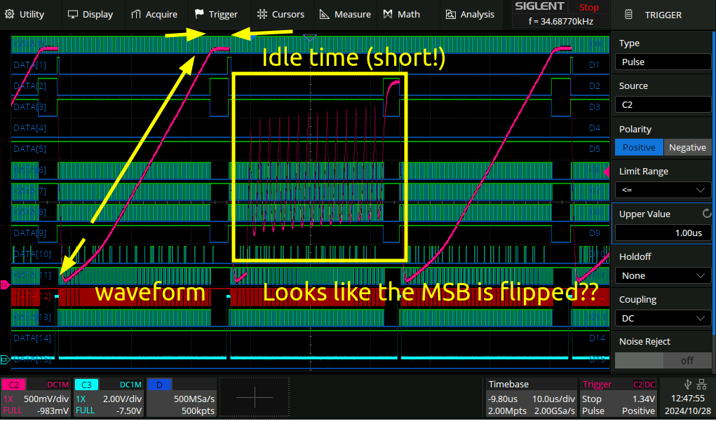
but as you can see there is still come wack stuff being output on the bus. Which brings me to the hot new 16 bit logic analyzer.
Siglent logic analyzer
fpga side:
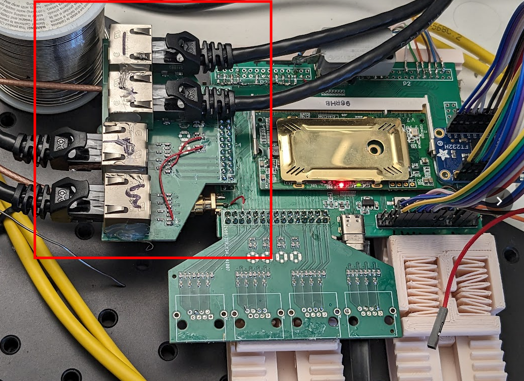
The actual siglent logic analyzer cable costs like $500 for some reason, so I made my own after forking someone elses. The repository for the gerbers and kicad files can be found here.
Bugs
Kicad actually somehow managed to lose the pcbdoc of the board that attaches to the scope itself. This is exceedingly annoying and not the first time this has happened, so I filed my first kicad bug here.
Ethernet
I decided to use ethernet cables here since they seemed the cheapest way to get 16 wires each with their own ground connection. My efforts at signal integrity were wasted however as there is quite significant crosstalk between the channels. Not really sure why that is, oh well. I hooked up as many ground connections as I could when laying it out. The reason that two of the connectors are flipped above is just that I got the layout wrong for half of them and they were connected to ground otherwise.
Debugging, enhance!
But anyway this gives me a new power. I can now examine simultaneously the 8 bit data bus alongside the 8 bit waveform bus to see where this corruption is coming from.
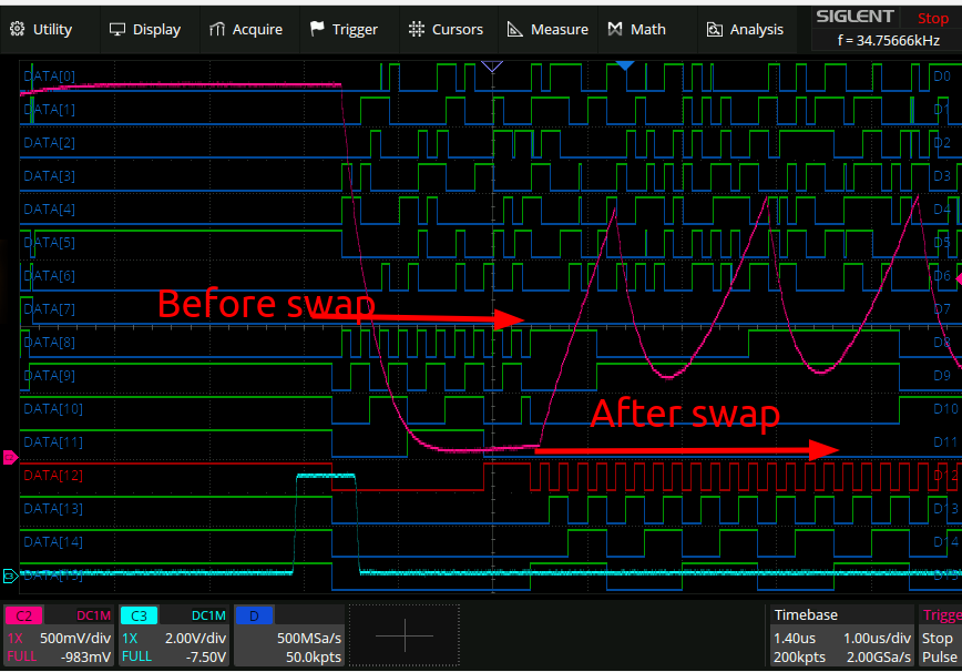
Here is what the command and waveform buses look like when a glitch happens:
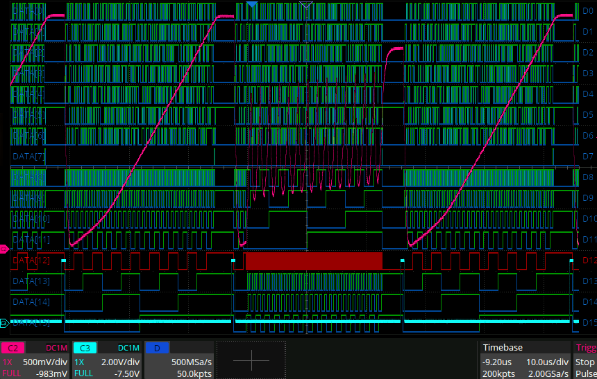
Someone went and swapped my nibbles!
Zooming in we can see it actually happened partway through the waveform, not from the very beginning: