Board
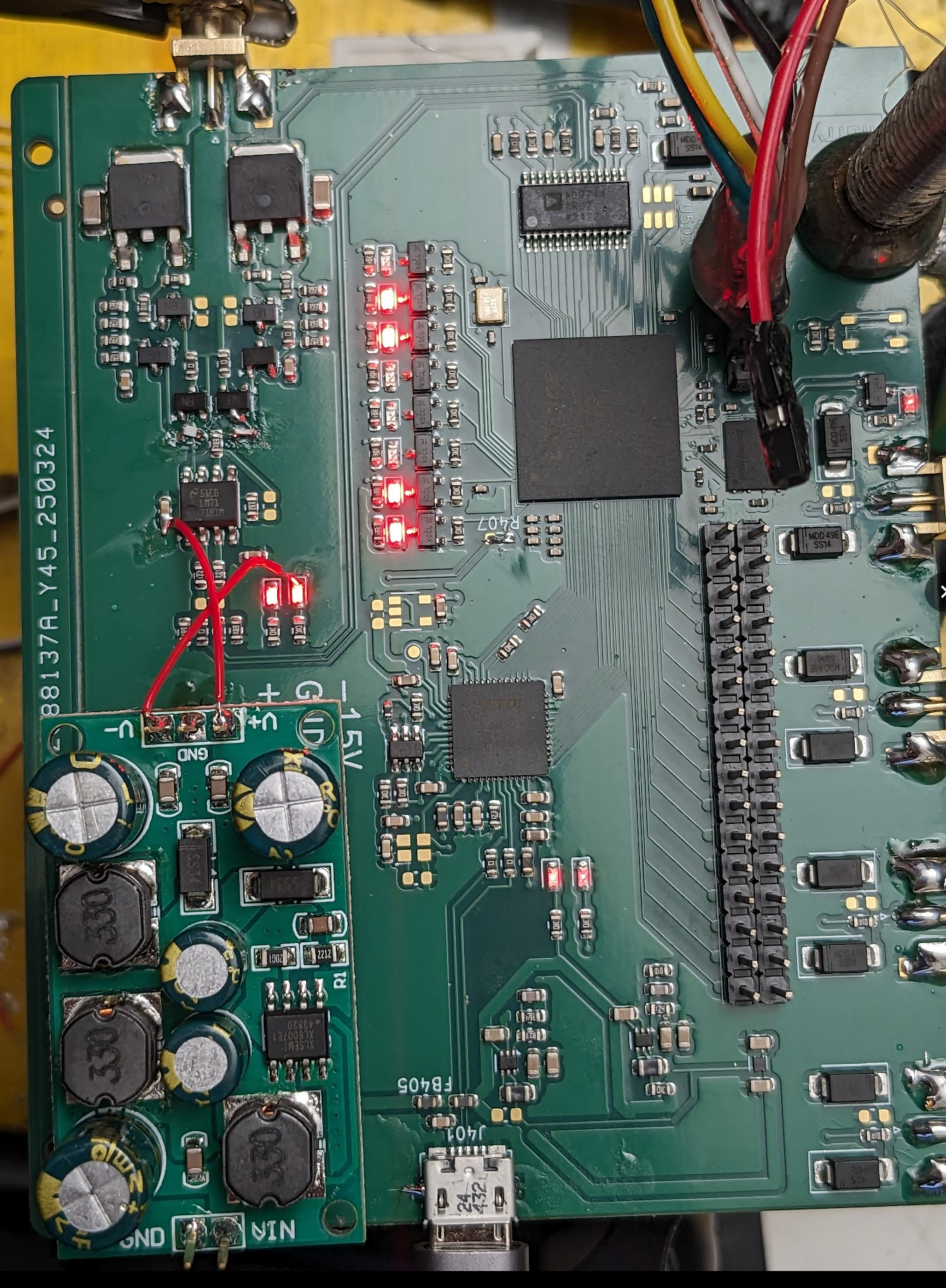
Everything programs and works out of the box with two exeptions: R407 which connects the PLL from the fpga to the FT232, and of course I got the 15V rails round the wrong way one the plug in module, though in my defence I noticed that prior to plugging it in.
Oscillation
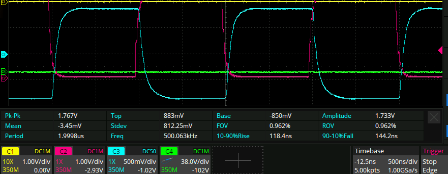
Only problem is the output of the awg oscillates, just like before. This only occurs when the output is unterminated, and is a bistable system: I can activate the oscillation by putting my finger in the right spot, and I can deactivate it by putting it in another spot. It has a good healthy amplitude:
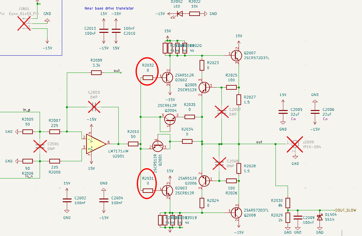
I tried increasing the value of the base resistors to 10R:
But that didn’t work.
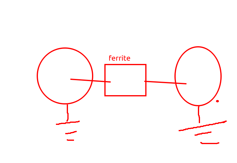
Ferrite bead VNA measurements
I have tried attaching ferrite beads to things before and have never observed them to be much different from 0 ohm resistors. Let’s take a look at what I have with the VNA.
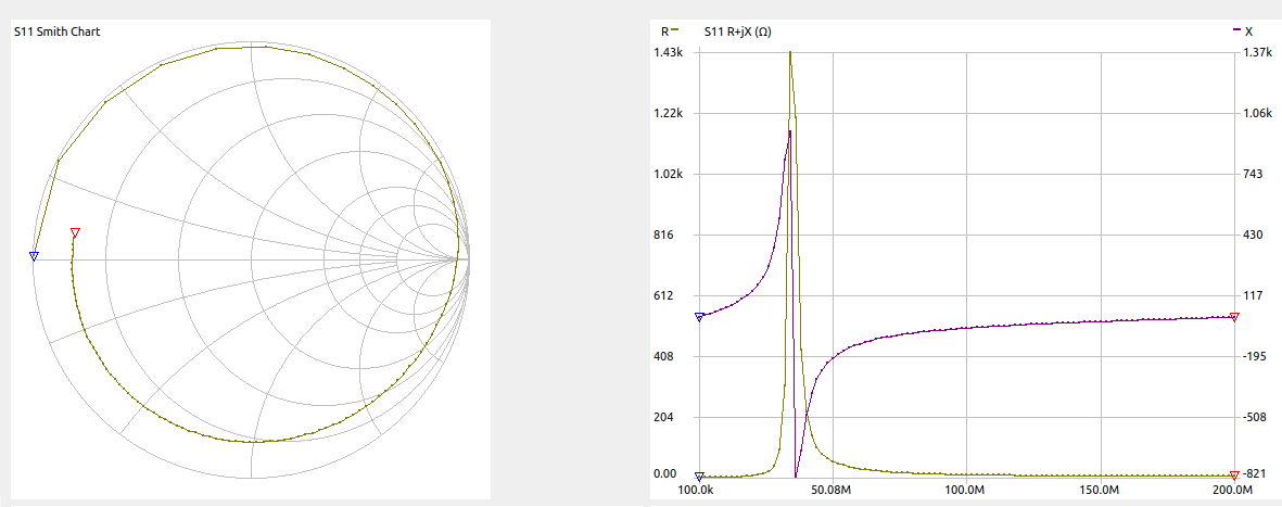
600R @ 100MHz GZ1608D601TF
One port measurement
Two port measurement
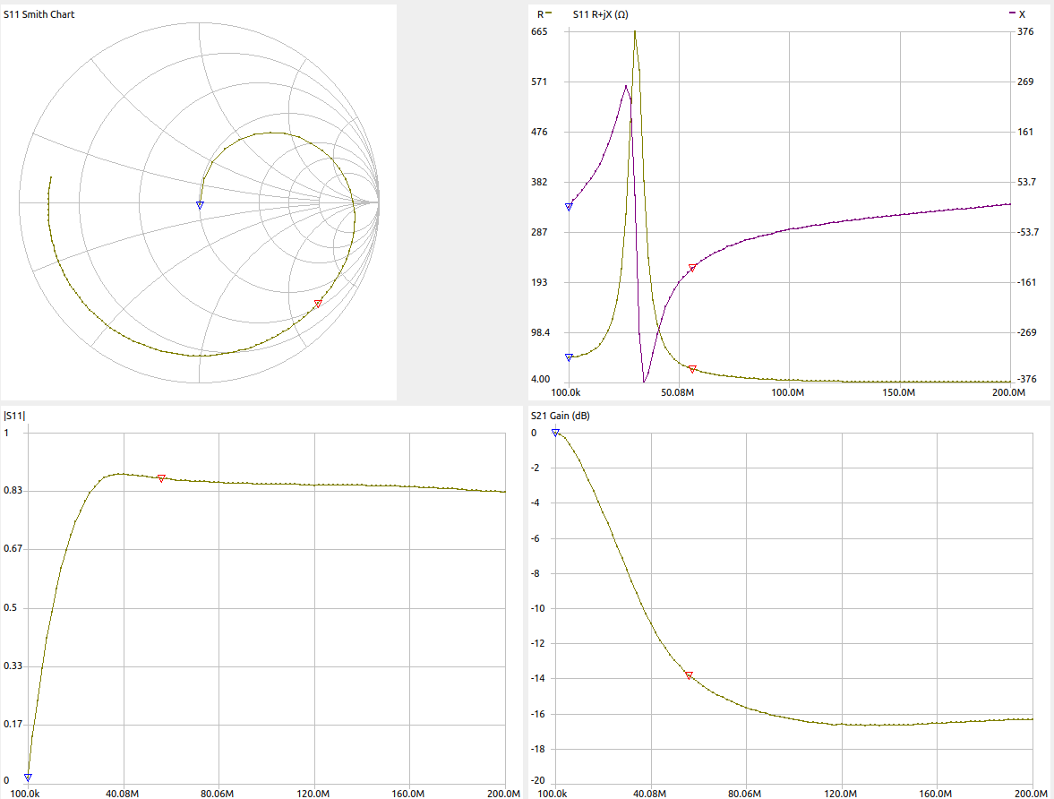
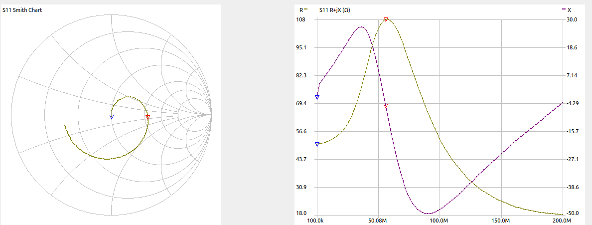
So I interpret the S11 and S21 together as:
- It’s close to an open circuit at 50MHz
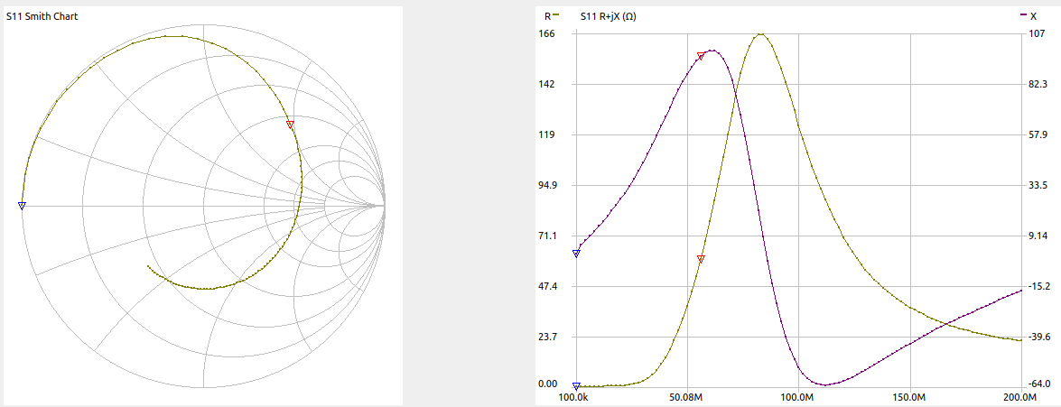
60R at 100MHz
One port measurement:
Two port measurement
Here the resistance peaks at 50MHz with 100R. That’s just what I want!
Back to the oscillations
Actually, completely removing the two resistors on the output of the diode from the circuit does not stop the oscillation at all!
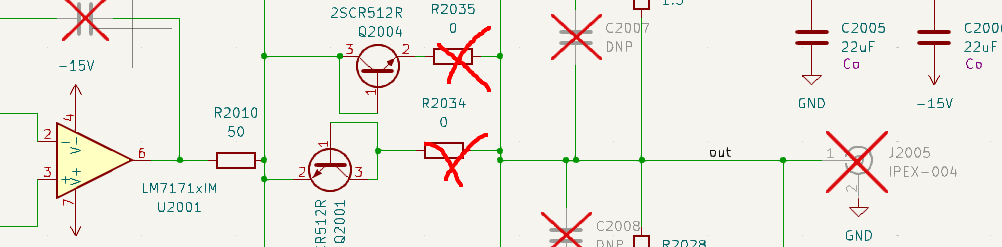
So it sounds like the feedback loop from the previous notes was a red herring. Going back to AN47 and following Ref 43 led to here which states clearly that the oscillation is simply a result of driving an emitter follower with a low impedance. So I put in a big bump to the resistor R2010 on the output of the op amp to 200R, and also added 4pF to the feedback of the amplifier, and now things look pretty good, with a rise time of around 50ns:
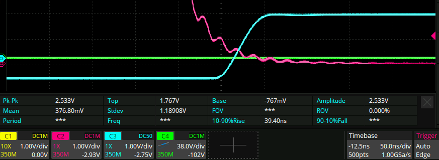
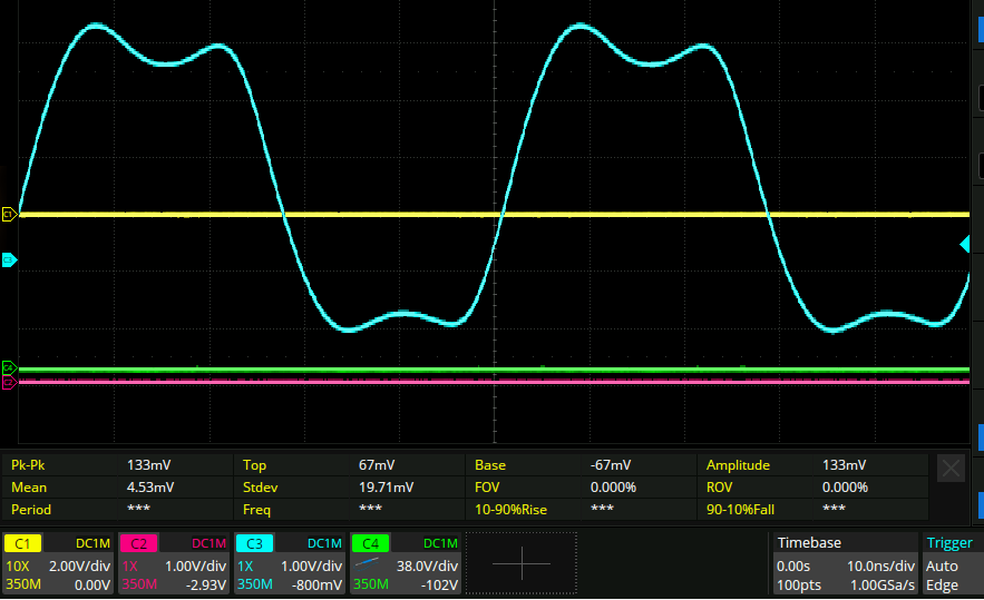
Into big signals though it seems a lot worse: