[top] checklist for next time
- pulldown for flash voltage
- pwm on gps lock pin for brightness
- Right thickness coin cell holder
- move the coin cell holder so a coin cell can be inserted without bumping into other components
- Move the coin cell holder further away from the compass since the battery is magnetic. Not strictly necessary with bias estimation, but desirable.
- wire up gps backup pin FET
- pulldown on gps FET input?
- Move USB connector so it isn’t right next to screen?
- wire up the enable line for the gps amplifier.
-
switch to lower quiescent current regulator? - Add accelerometer
- Add an ambient light sensing LED
- add resistors in line with power rails to easily turn on/off different chips
- remove the board cutout for wifi.
- Add in user button for no particular reason.
- make sure pcb can be powered from a phone with usb c connector in both orientations
- update “plug into power bank” text to explain you can use a phone
- Update notification LED text
- put in user button.
- move the USB C connector down the bottom, like a phone
- round the corners on the PCB
- Figure out why the first time it’s powered on to a power bank, it just hangs.
- make is so that when the board is booting, the LED’s are off.
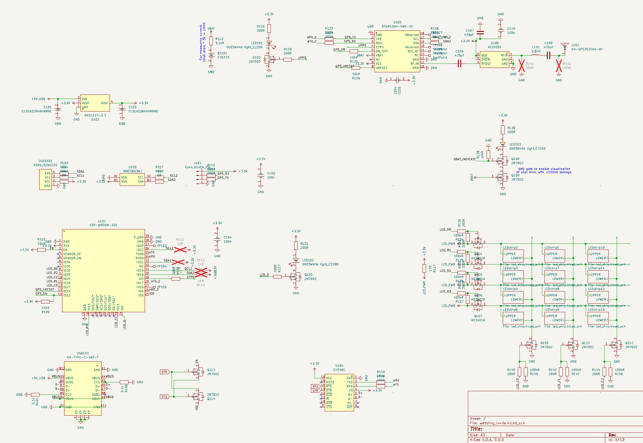
Schematic
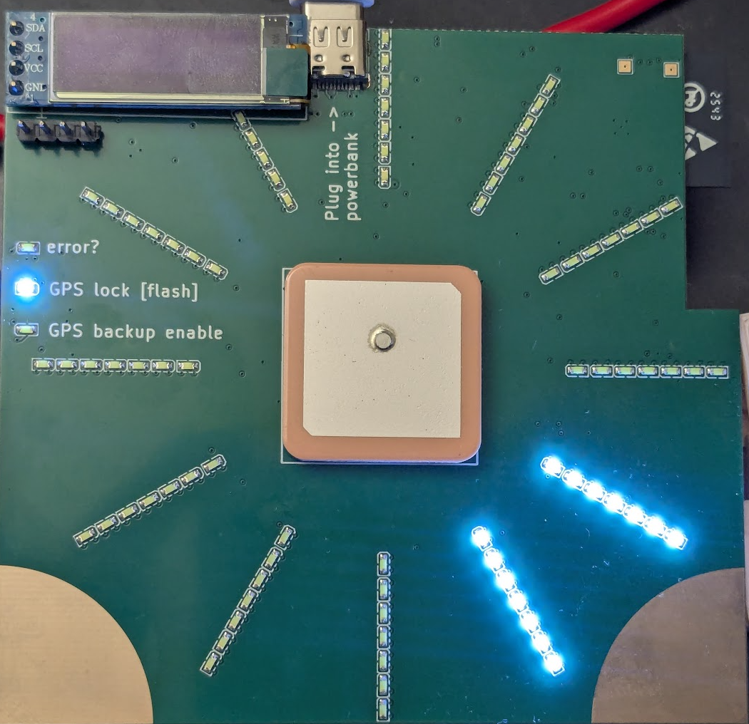
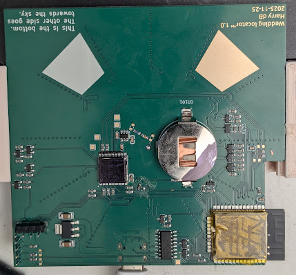
The PCB
Bringup
I pasted images of the schematics into Gemini 3 and asked it to come up with a bringup arduino sketch. It got a couple of the pin numbers wrong, but so far I have turned on the debug LED, flashed all the LED’s in the LED matrix, and the I2C scanner alleges to have found some thing at 0x3C. Nice.
GPS backup pin
I put this circuit in to be able to see if the backup pin was in:
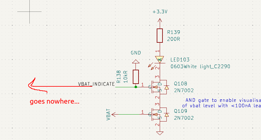
Missed actually wiring this to the esp32. should have put a very weak pulldown on vbat, too.
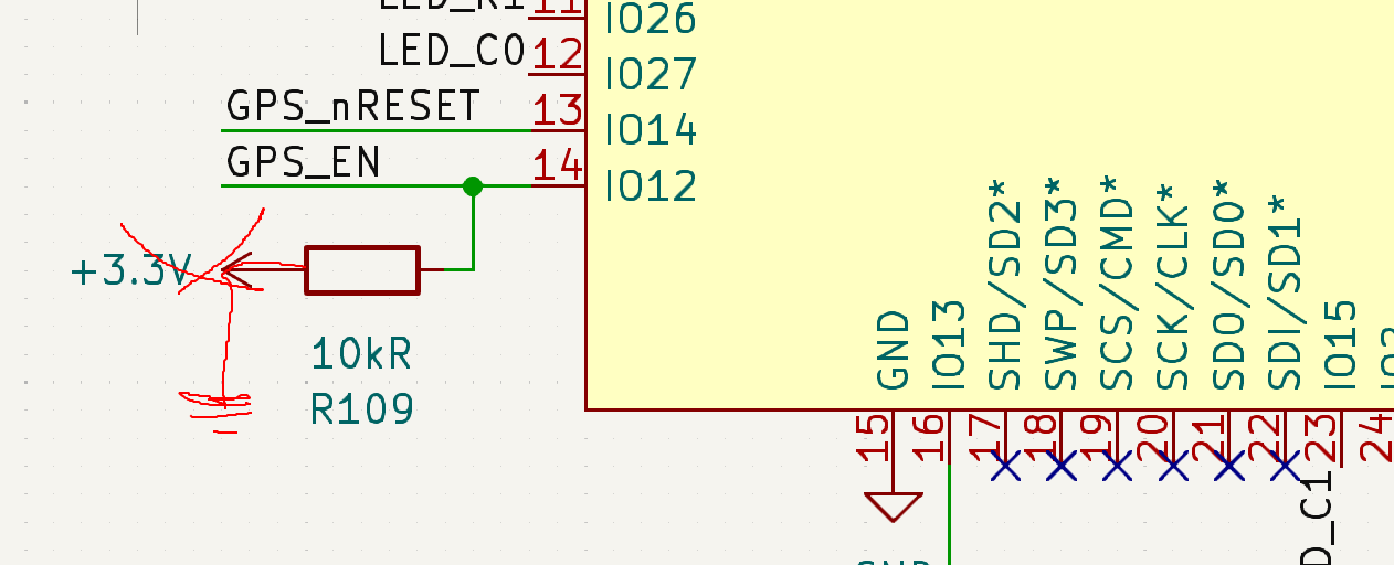
Flash pin
When I pasted the schematics in for a design review, gemini also pointed out that GPIO 12 was read on bootup to set the voltage of the internal flash, and so I could not use it to drive the LED matrix. Nice catch. I don’t know if I read the subsequent recommendation properly, but anyway I put a pullup on IO 12 when I should have put a pulldown instead. oh well.
I2C display and GPS
Boom.
Both work out of the box. Nice
Compass
This is where the troubles start. You would expect nothing less from a compass. The default arduino library for the compass (MMC5603NJ) I am using does not actually measure the magnetic field very well, because the default measurement includes all the internal compass offsets. These offsets are huge and make the sensor useless out of the box. Instead to get a real measurement the datasheet says you have to do this to get a “bias-free” measurement:
bool Adafruit_MMC5603::getEventNoOffset(sensors_event_t *event)
{
  // 1) SET
  _ctrl0_reg->write(0b1000);
  delay(1); // REQUIRED: t_SR = 1ms per datasheet

  // 2) measure
  sensors_event_t event1;
  if (!getEvent(&event1)) return false;

  // 3) RESET
  _ctrl0_reg->write(0b1'0000);
  delay(1); // REQUIRED: t_SR = 1ms per datasheet

  // 4) measure
  sensors_event_t event2;
  if (!getEvent(&event2)) return false;

  // 5) result is (e1 - e2) / 2
  *event = event1;
  event->magnetic.x = (event1.magnetic.x - event2.magnetic.x) / 2.0;
  event->magnetic.y = (event1.magnetic.y - event2.magnetic.y) / 2.0;
  event->magnetic.z = (event1.magnetic.z - event2.magnetic.z) / 2.0;

  return true;
}
Which seems like a pain. I put in a pull request here to add the method, we shall see if it is accepted.
Even with these biases removed, the results are not great. There is still up to a 40 degree heading error. I’m sure it could be removed via further calibration but that is not a rabbit hole I wish to go down.
LED brightness and ambient light
The LED’s are bright. Too bright.

So I asked mr gemini if there were any parts in jlcpcb’s standard parts catalog that could be use to detect ambient light, and it suggest the ol ‘led as a photodiode’ trick. It had a good method too which I would not have thought to use: reverse bias the photodiode then switch your digital pin to input. This charges the LED capacitance and so the discharge time is dependent on the photocurrent from the LED. Brilliant, Dan Gelbart would approve.
Anyway I hooked it up and it works great, it takes 6000us in close to complete darkness and 2us with a phone torch pushed up against the LED.
Power draw
The power draw of this thing with the gps and the oled screen ostensibly off, with the esp32 doing nothing in the main loop, is 70mA. That’s pretty bad if we want to be able to run this thing off a AA battery for a long time.
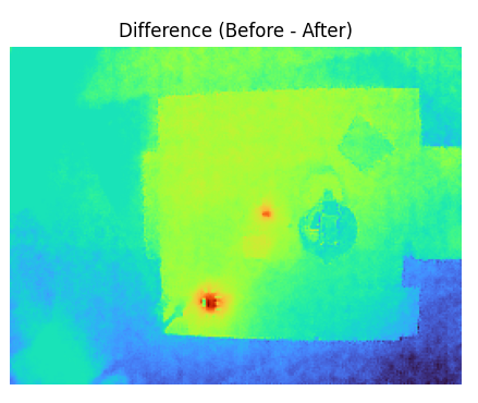
Like a fool, I did not properly connect my devices to current sense resistors so I can’t easily tell how much power they are using. But at 70mA I should be able to see with a thermal camera, especially if I diff the measurements.
Diffed thermal measurements
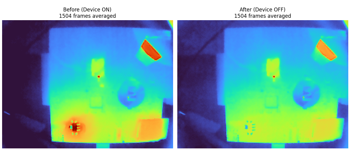
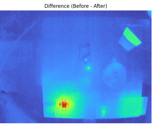
So it looks like there aren’t any surprises. The GPS indeed turned itself off, which is good. Other than that it’s just the linear regulator, the esp, the amplifier for the gps, and the usb to serial converter. The linear regulator looks like it’s drawing a lot of power. But it’s 70mA powered off 5V, and about 70mA powered directly off the 3.3v line. So I don’t think that the linear regulator has a lot of quiescent current.
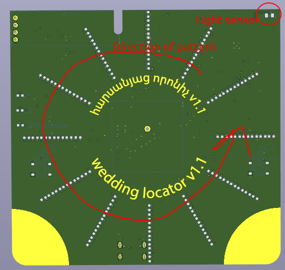
I put a cloth over the thermal camera setup to try and eliminate the effect of reflections, but the gold plated tap in the top right still showed up.
Desolder till the power is gone
- remove esp32 ground lead: 30mA
- remove gps ground and short indicating leds fets to ground: 20 mA
- remove usb to serial chip ground: the same, 20mA
- power the above off the 3.3v rail directly to eliminate the linear regulator: same, 20mA Here is what the diff thermal image has to say after the above desoldering whilst powering the board of the 3.3v rail:
Looks like the linear regular draws a bunch of current just being attached to the 3.3v rail, with nothing on the 5! After desoldering the linear regulator the draw goes down to 10mA. then after desoldering the gps amplifier, finally the draw is down to 0.
- soldering the linear regulator back on goes up to 16mA
- Then putting the amplifier back on it goes up to 21mA. Doesn’t quite add up but I am at the very bottom of my flukes current range as I have blown the 400mA fuse as I always do.
- Attaching the usb to serial takes things up to 24mA
- Then switching to the 5V supply it goes up to 27mA
- Then adding in the esp32 it goes up to 52mA
- Changing the arduino script so the only thing it does in the main loop is sleep doesn’t change the power much, is 55mA
- Moving the enable line back over to the esp32 (so it’s always on) takes the power up to 79mA
- Then putting the OLED on, it goes up to 81mA. This gladdens me, means the system can run in an overall very low power state if I could get the esp32 sleep right.
- Enabling the compass indoors at night in a well lit room, the current is still around 80mA
- At full brightness the total power draw is 103mA
Back to compass
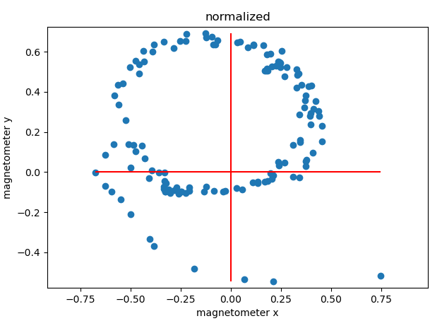
The compass seemed like it was working reasonably well earlier after I implemented the code that reset/flipped the measurement each time to cancel out the bias. But after getting on a plan and waiting a few days, the measurements are back to pretty useless. Here is a scatter plot of the measurements over the x/y axes when rotating the compass:
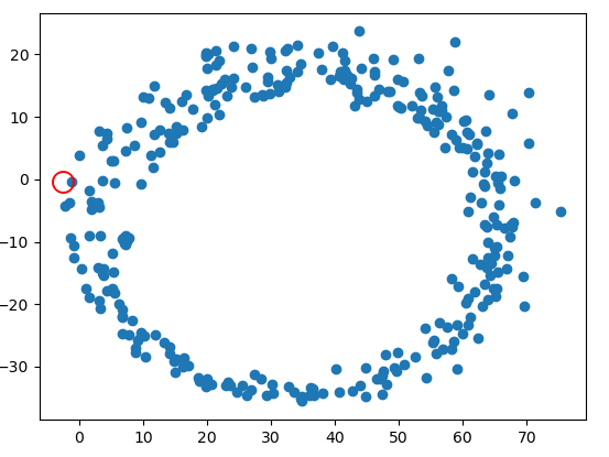
If there was no bias remaining, the compass measurements would be centered around the origin.
CR2025
The CR2025 backup battery is right next to the imu. I just discovered it’s also magnetic!
Here are some magnetic readings taken with the battery removed:
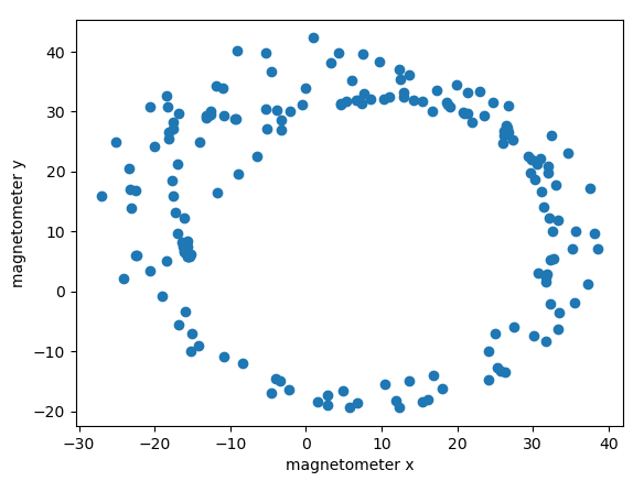 Still not that great
Basic calibration
It was inevitable that this would be required. Here is a super simple calibration class:
class CompassCalibrator {
public:
  CompassCalibrator() {
    mins_ = {1e9, 1e9, 1e9};
    maxs_ = {-1e9, -1e9, -1e9};
  }

  void AddObservation(sensors_vec_t obs) {
    constexpr float kEarthField = 50.0; // Typical Earth's field ~25-65 µT

    if (magnitude(obs) > kEarthField * 2) {
      Serial.println("Warning: Magnetic reading exceeds 2x Earth field - possible interference");
      return;
    }

    sensors_vec_t old_mins = mins_;
    sensors_vec_t old_maxs = maxs_;
    mins_ = elementwise_min(mins_, obs);
    maxs_ = elementwise_max(maxs_, obs);
  }

  sensors_vec_t calibrate(sensors_vec_t in) {
    return ((in - mins_) / (maxs_ - mins_) + (-0.5)) * 2.0;
  }

private:
  sensors_vec_t mins_;
  sensors_vec_t maxs_;
};
Which leads to these results:
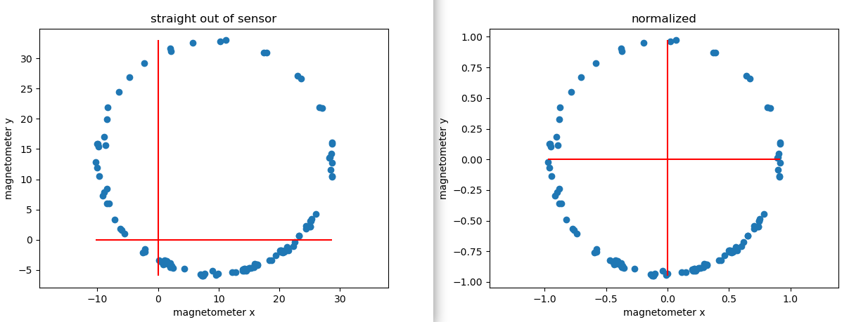
Seems pretty good. The measurement kind of messes itself up a bunch if you go near a piece of iron though which is an issue. the above was also taken under super ideal conditions with perfect rather than handheld rotation. for example after putting the compass down on a table with a metal support underneath it, you get this:
…significantly less idea.
An accelerometer is needed.
Reliable heading estimation isn’t going to work unless the PCB is never tilted from the horizontal. The component of the magnetic field in the vertical direction is large, larger than that in the horizontal direction (for many locations at least). This means that when the PCB is tilted, the measured min/max components of the x/y field are much larger than they otherwise would be. So the offset subtraction does not work, as it is contaminated by the measurement in the vertical z direction.
Since the location of the pcb is known from the gps, the expected magnetic field vector can also be calculated. But, this does not get us all the way. As Mr GPT puts it:
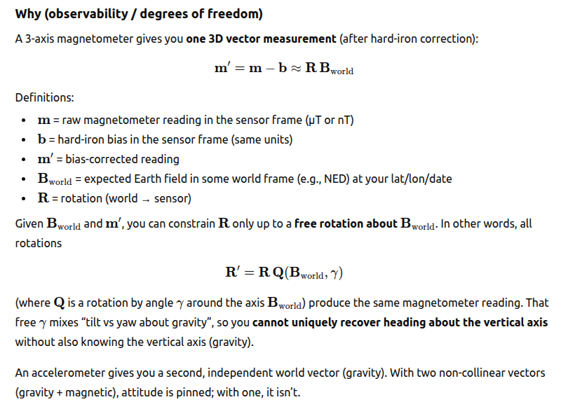
Add an accelerometer.
I have now added:
- Tilt compensation with an accelerometer
- A new way of estimating the bias that is robust to outliers. Specifically the new algorithm for estimating the bias is to maintain a rolling 20 sample buffer of compass measurements. New compass measurements are only added to the buffer if they are >10 uT from any of the other measurements in the buffer. A sphere is fit with least squares to the 20 measurements. This is mildly robust to outliers when they are introduces, but crucially as the compass continues to be used new estimates are added that push the old ones out. That way a single bad measurement can’t corrupt the bias forever, as the old (max + min) / 2 method did.
This new method results in a fit with an rms error of ~1 degree, which is nice.
GPS odometer
I figured a fun thing to have would be an odometer, measuring how far you have moved whilst the PCB is on. This gives a better sense of progress than seeing the distance to the wedding change from 9000km away to 8999.9km away.
Problem: A stationary GPS signal wanders around at about walking speed, so you will accumulate many km of distance with the pcb just sitting on the desk. I tried to mitigate this in a similar way to the magnetometer calibration by having a buffer of N lat/long pairs, and only incrementing the distance travelled if the new lat/long is far away from every single other element in the buffer. That way if the position wandered around without too much drift, the wandering positions would not accumulate.
This doesn’t seem to work though. A further investigation plotting the GPS position as a function of time overnight with the PCB sitting on a desk gives this result:
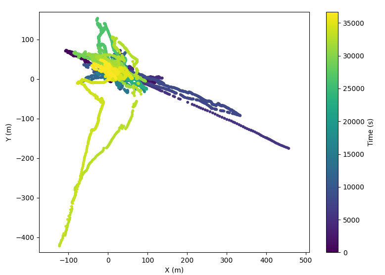
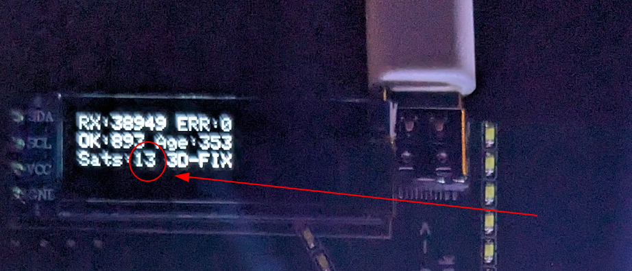
What garbage. What utter trash. I really don’t see how the drift could be hundreds of meters! Now mind you the gps antenna here was indoors next to a window, so the gps signal was probably not that great. There seem to be 7-11 satellites connected though, so the error still seems high to me.
Checking supply rail during the set/reset compass measurement
|Earlier when the set/reset measurement method did not completely remove the bias, gemini suggested that this might be because my schematic did not include an appropriate amount of decoupling per the datasheet (true) and that therefore maybe the supply rail was drooping during the measurement. Probing of the rail however reveals that any droop is <100mV, so I don’t think that this is the case.
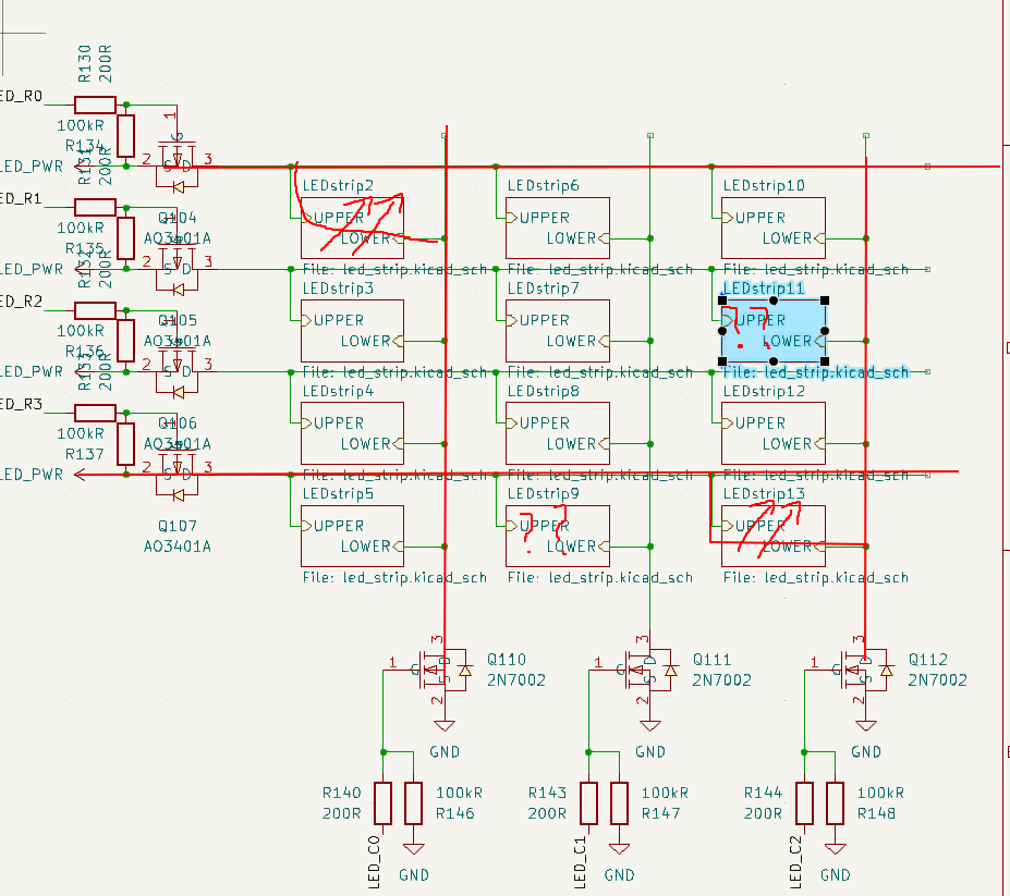
LED bar mystery.
GPS backup power
The GPS module states that it draws 10uA from the backup supply:
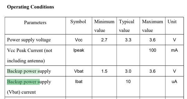
However I cunningly put a 5.1kR resistor in series with it when I made the schematic, and so I am able to measure that since there is a 3.3mV drop across it, in fact it only draws 3.3e-3/5.1e3 = 725nA, considerably less. This means that a CR927 battery should be quite sufficient.
LED interpolation
I finally decided to add LED interpolation, whereby the brightness would be interpolated between two adjacent LED bars based on the true heading of the compass, rather than snapping to the nearest bar. It took ages for mr Claude to get this right, and it ended up taking the i2c peripheral to send out sychronous gpio edges on all relevant gpio lines. This was because otherwise you have to to time-slicing between two adjacent LED’s, since it’s not possible to light up only two LED’s at once in an LED matrix, if the LED’s share neither a row nor a column:
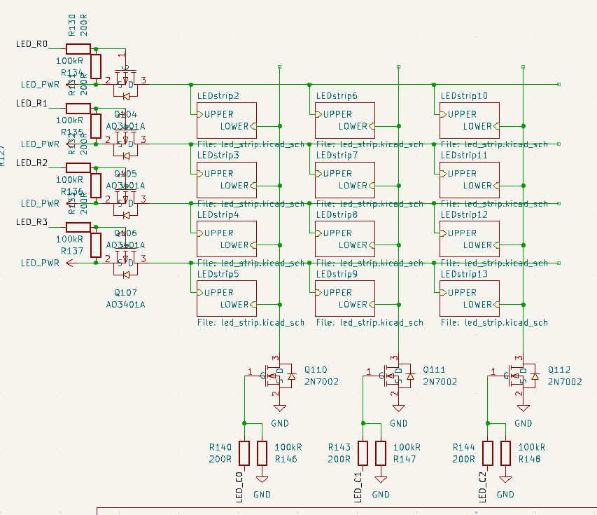
As if you try that, you get 4 LED’s lit up. So there were a bunch of interactions with the PWM peripheral where the pwm edge would only be updated after the end of a pwm period, and then when you switched between LED bars this would cause a momentary glitch on the other LED’s and blah blah blah.
Brightness consistency
To my eye, the interpolation between adjacent LED bars was not perfect, there was some variation in brightness. Fortunately since we have an ambient light sensor this is easy to measure by just putting the PCB in a box. This results in these plots:
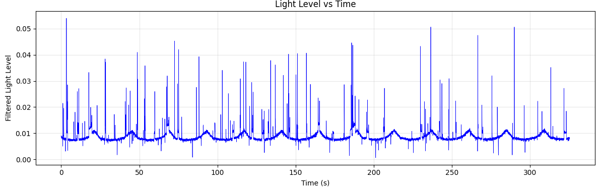
Easy to see the pattern here, though there is a bunch of random spikes in the signal for some reason.
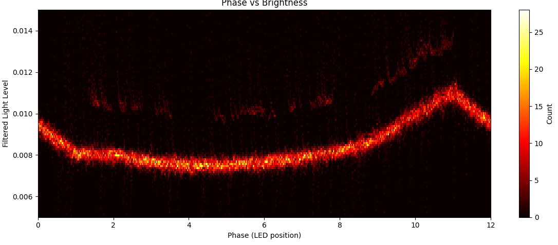
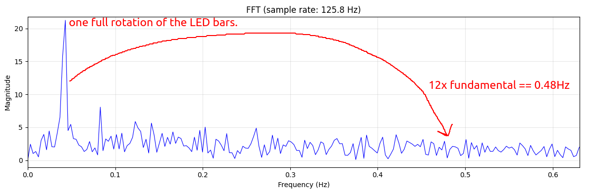
However it appears my eyes tell a lie - The the overall rotational speed of the pattern itself is clearly visible, but the interpolation between adjacenet LED’s is not. The LED is in the corner of the PCB, and so the brighness varies periodically as the pattern rotates:
But if you look at the FFT of the brightness, there is absolutely zilch at 12 * the overall speed. So this means that the overall brightness is not changing as the LED rotates.