Following on from here the ideal pressure sensor for this engine would look something like this:
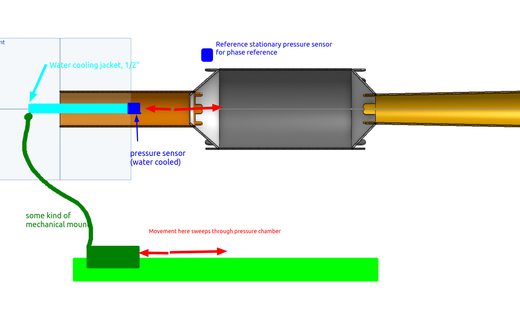
You can’t do this with most pulse jets or engines, but you can with this one: a single high bandwidth pressure sensor on a linear rail swept through the inlet, combustion chamber, and outlet, should enable us to get a pretty complete characterisation of the engine. Most pulse jets in the lab get a couple of pressure sensors down the length of the engine. But if you could sweep a single pressure sensor all the way down the inlet + combustion chamber you get the full pressure(t, x) function instead of just pressure(t, x0, x1… xn) for a very small n since you have to buy + install each sensor.
If we put a stationary pressure sensor on the outside, and listen to the fundamental frequency of operation of the pulse jet we will also be able to get phase information too. This external pressure sensor just has to pick up the fundamental so I think a standard microphone will do.
Linear rail
I’ve been furnished with this:
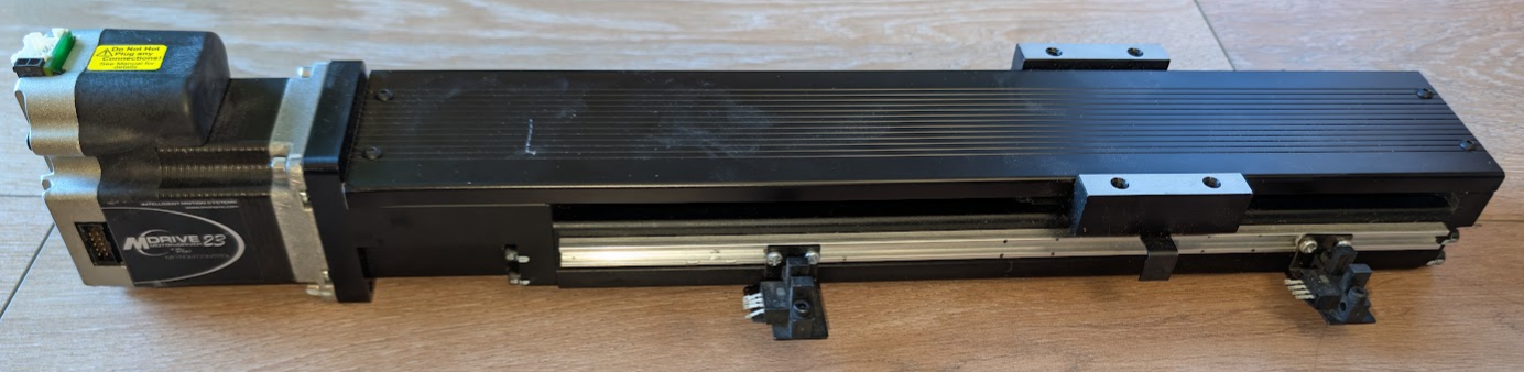
Which should be just the ticket. Should be pretty easy to get mr claude to figure out the interface.
Interfacing
here is what claude came up with for the interface to this thing in terms of connectors and setting up the opto-interruptors as limit switches using the gpio ports on the driver. Ordered a bunch of stuff off digikey on that basis, let’s see how it goes.