Finally the pulse jet, linear rail, pressure sensor, and associated acquisition system is ready.
It looks like this:
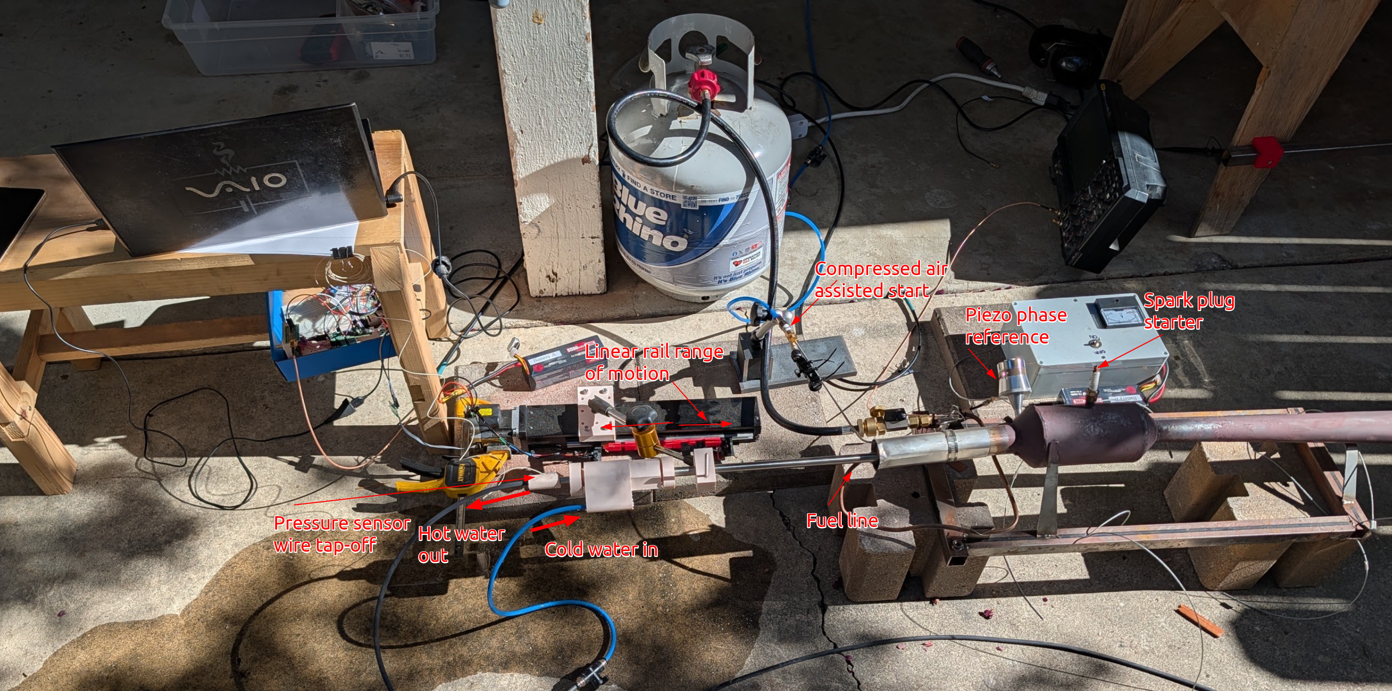
Now to measure the pressure. As a reminder this is what conceptually is supposed to be happening:
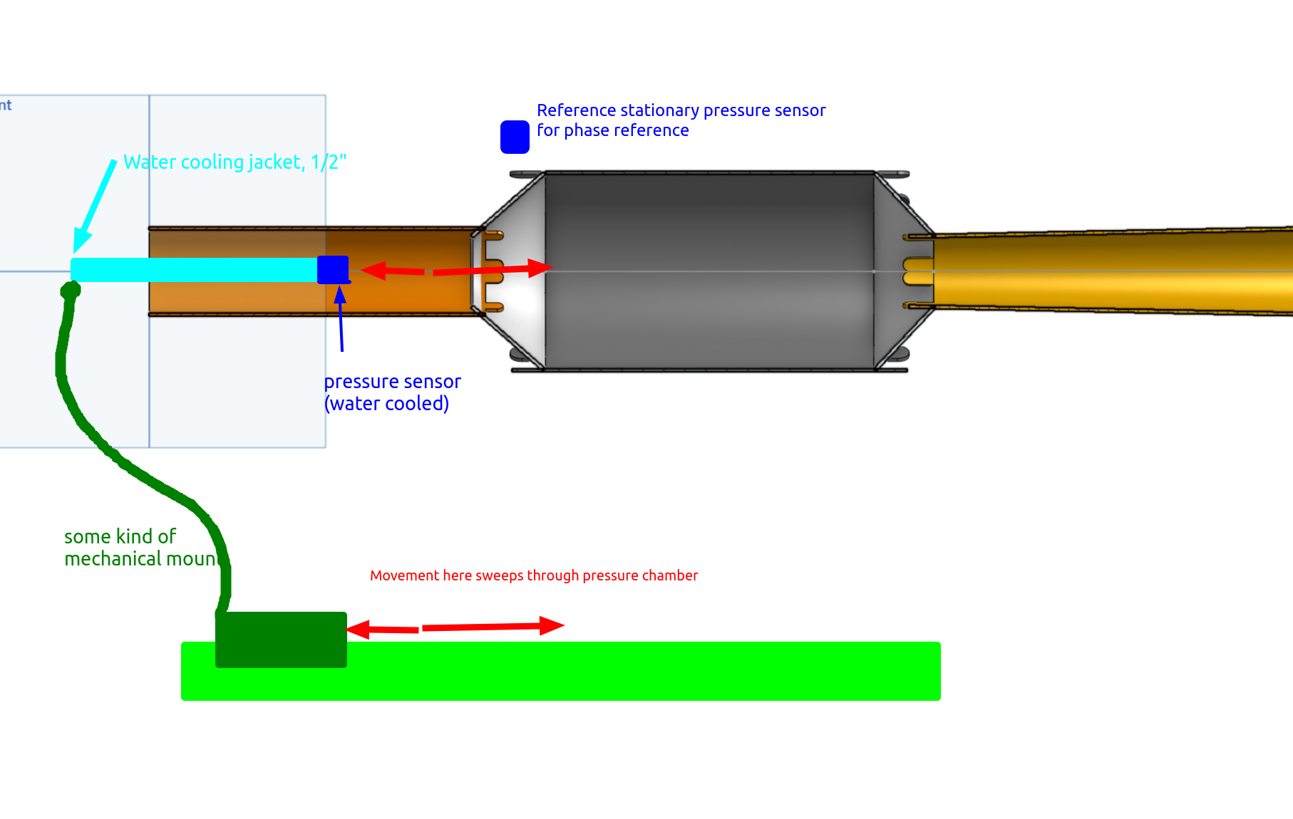 When the pressure sensor is swept back and forth, it will measure a periodic pressure wave of course. Just this by itself is useful because it tells us the frequency and amplitude of the pressure wave, as a function of distance inside the pulse jet. But, we can do better. By placing a stationary reference sensor on the body of the pulse jet we can measure the phase of the pressure sensors measurement with respect to the reference. This means that the propogation of the pressure wave down the inlet can be directly measured.
To elaborate: suppose you have an imaginary pulse jet. Every 1ms, there is an explosion in the combustion chamber and a shockwave propogates down the inlet. If all you had was the pressure sensor, you could place that sensor at any point down the inlet tube, and you would obverve a repetitive spike each time the shockwave passed. But you would not have any way of observing how fast the shockwave moved down the tube. By contrast a reference pressure sensor placed on the side of the combustion chamber will observe the spike at the same time always, relative to when the spike happens. So now by moving one pressure sensor around, and observing when the pressure spike happens relative to the reference sensor, you can actually measure how the pressure spike is propogating down the inlet tube.
Here is a gif from claude to illustrate what I am talking about:
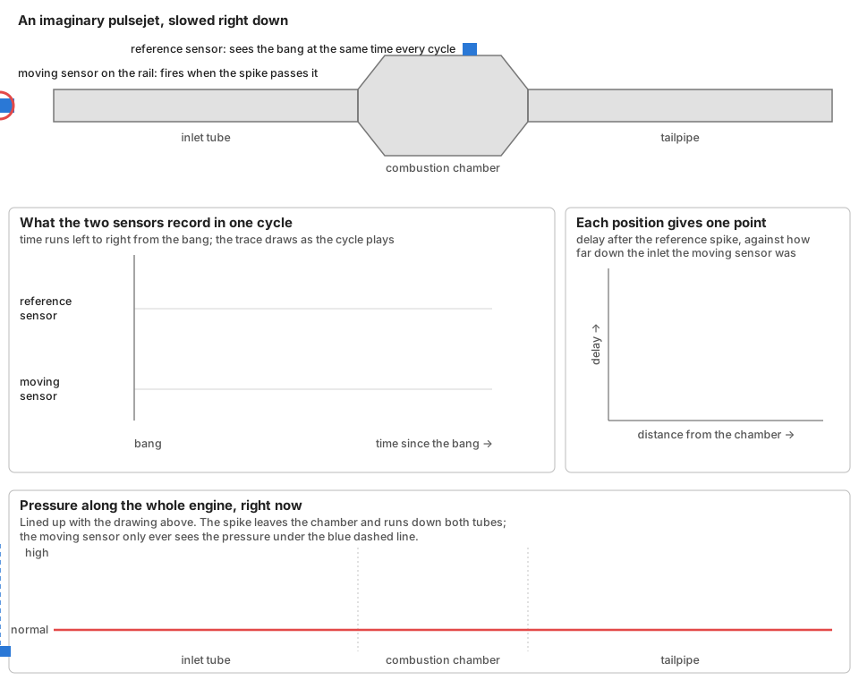
Now the thing about the bottom plot is: for a completely linear combustion chamber like mine, it should (hopefully) more or less completely characterise what is happening in the engine. And, it’s also pretty trivial to get the equivalent plot out of a simulation. So this will be used to first ground a simulation so it matches what I have “Claude: make only principled adjustments” and then the sim can be tweaked to optimise it.
Overall data
Looks good
Odd pressure spikiness
Throughout parts of the run, this weird stuff happens:
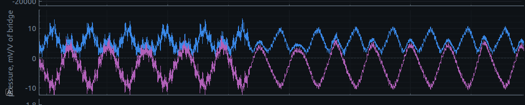
Why is that? no idea. Doesn’t really fit with my idea of a loose connector.
Dying pressure sensor
Here is the piezo pickup used the first time, bullclipped on with a random woodchip as a load spreader in an attempt not to crack the piezo element:
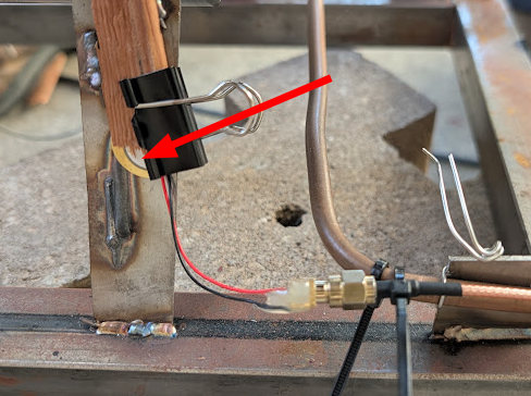
This worked reasonably well for one data recording, then died and did not work well for another.
So, we bolted a proper ultrasonic transducer on:
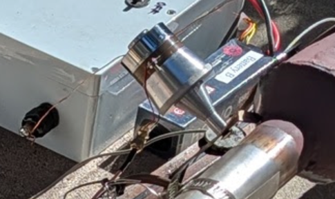
This also worked well for one recording, and then also very clearly died slowly over the course of a run:
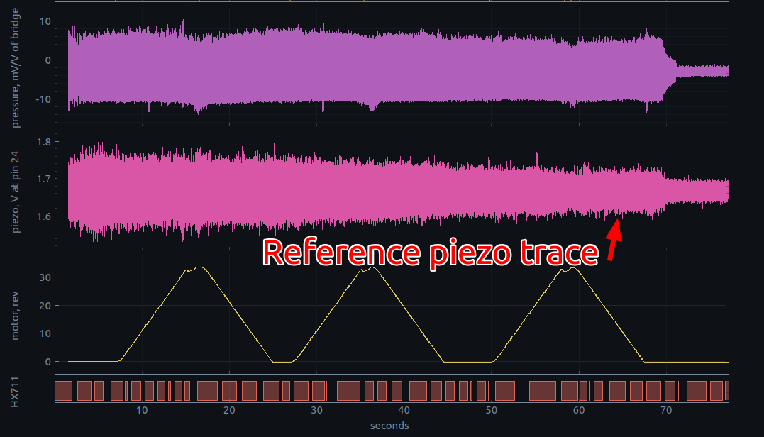
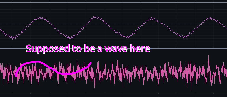
By the end, it was practically dead and you couldn’t really pick up on the reference waveform at all, here is a zoomed in trace from near the end:
Claude visualisation
Link here