Most of my understanding of metal detectors comes from the highly excellent book “George Overton, Carl Moreland - Inside the Metal Detector-Geotech Press (2016)“. It is assumed reading.
Problem
Current commercial metal detectors are extremely simple, so much so that it seems likely to me that something can be done to make them dramatically better. They remind me of the radar days of yore when one took an oscillator, fiddled about with it a bit, received a signal, then applied the amplified result to a CRT screen and expected people to detect planes with it.
The limitation on performance of a modern metal detector much of the time as I understand it is “signal to ground ratio”. There is some signal coming back from a piece of metal in the ground, but it is mixed in with lots of ground, which can contain magnetic iron oxides and whatnot. The term of art here is “signal to ground ratio”. If you have a metal detector with some kind of transmit coil like so:
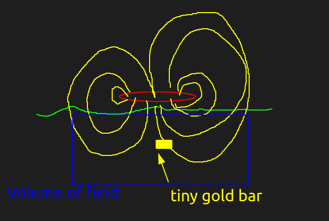
So the huge volume of the field in the ground compared to the thing you are measuring means that your receiver just measures ground clutter. You can’t “focus” magnetic fields in any meaningful sense, so this is an inherent limitation of the system.
Getting around inherent limitations of the system.
Integration
One of the things you might think about doing is introducing the notion of the position of the coil. If you know the position of the coil you can integrate the signal over space and do things like try to subtract the ground offset. People already have gross “ground balance” stuff to subtract out the overall field, but as I understand it the ground at some point becomes sufficiently heterogeneous that the remaining wiggles in the signal as you move the coil around swamp the signal from the gold. Again, what you are basically doing is taking a huge spatial lowpass filter (30cm wide coil) and moving it over a bunch of much smaller things (rocks and tiny bits of gold).
What we need to do conceptually is make the magnetic field into a spike that goes into the ground.
Field shape alteration
Consider the following setup: instead of one transmit coil, you have two coils next to each other with a receive coil in the middle. Let’s ignore for the moment the notion of induction balance. Here is a top down view:
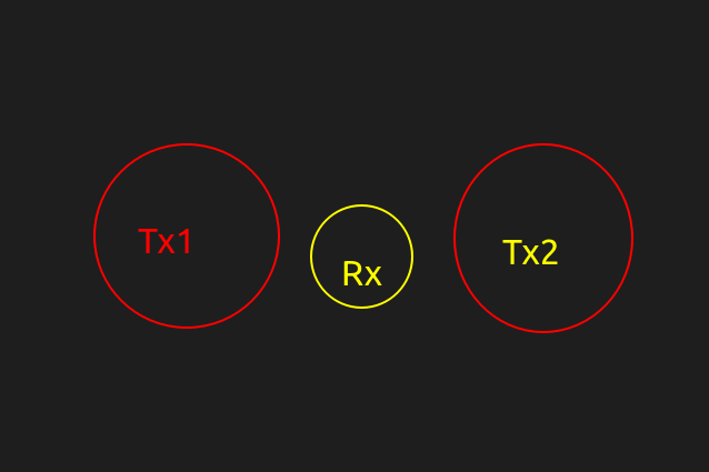
Now let’s imagine what the rx would see for two different scenarios:
- Tx1 and Tx2 have currents going in the same direction (say both clockwise)
- Tx1 and Tx2 have currents going in the opposite direction (say both anticlockwise)
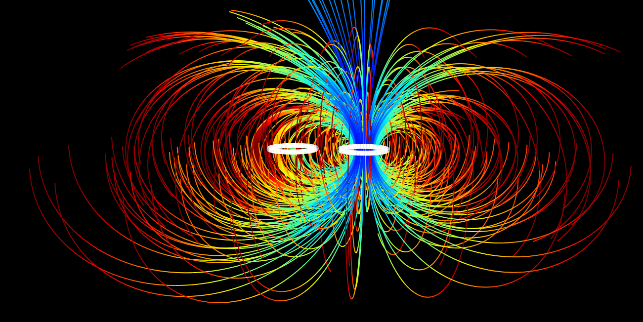
Both positive visualisation:
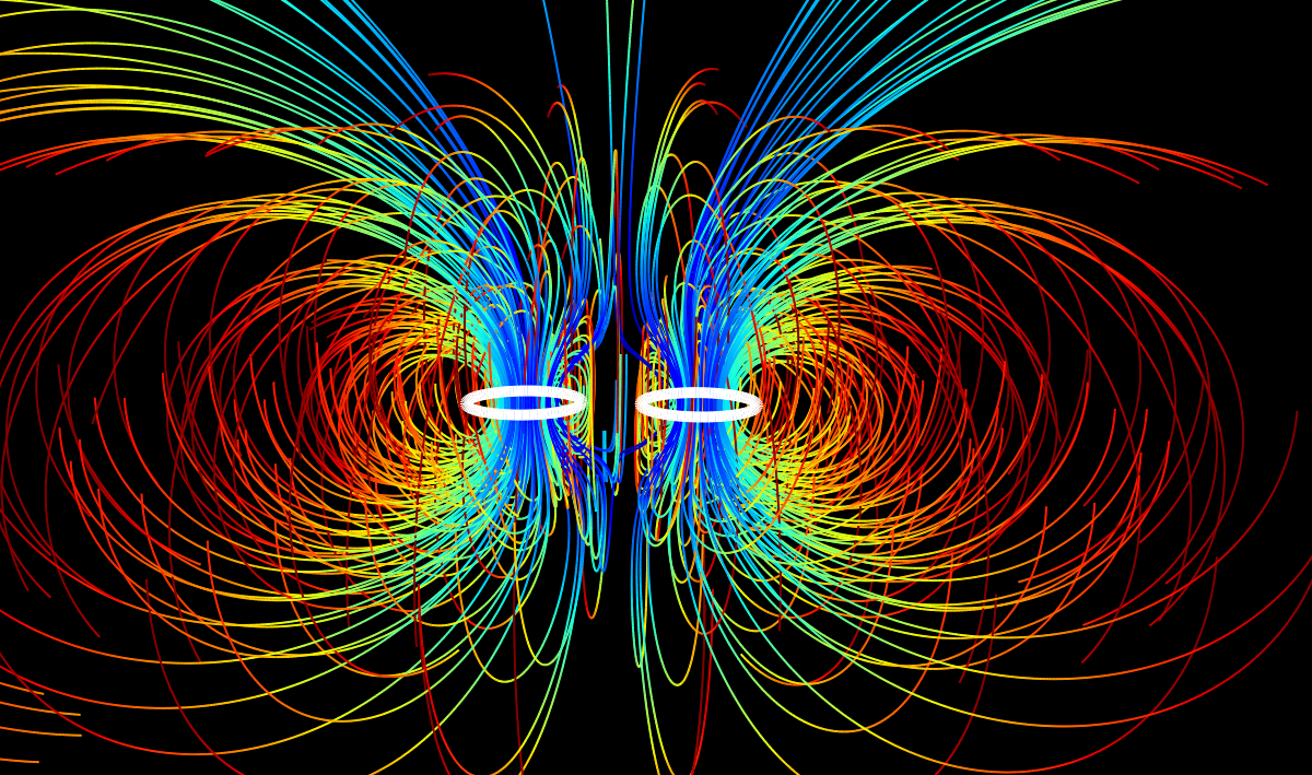
One positive one negative
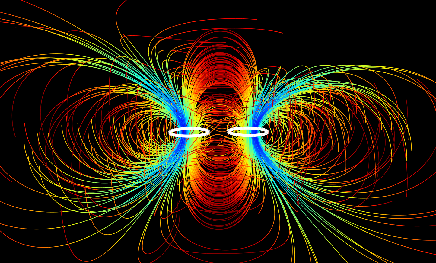
Let’s imagine now that there is a target in the ground directly between the two tx coils, but down a bit. For the ++ case, the target would see a magnetic field with components mainly in the vertical direction, similar to a normal detector with a single coil. For the +- case, the target would see a magnetic field with components in the horizontal direction only. The field outside the radii of the two coils looks similar in both cases
So from the point of view of the receiver in the ++ case it would get signal from the target, and in the +- case it should see no signal at all, since the induced currents are perpendicular to the receive coil.
Now, what would you see if you took Rx(++) - Rx(+-). The parts of the receive signal originating outside the extent of the two coils would be mostly cancelled, since the magnetic field looks similar in both cases. The components originating from between the coils would not however!
here is a diff of the above two vector fields:
Wait what. That’s just the coil that switched polarity! (a + b) - (a - b) = 2b, duh. I wonder if this actually invalidates anything…
Measurements
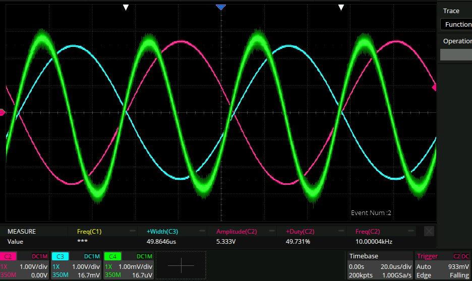
+- case balanced
Here I have balanced things down to the difference in the second harmonic coming from the signal generator: