Need.
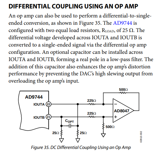
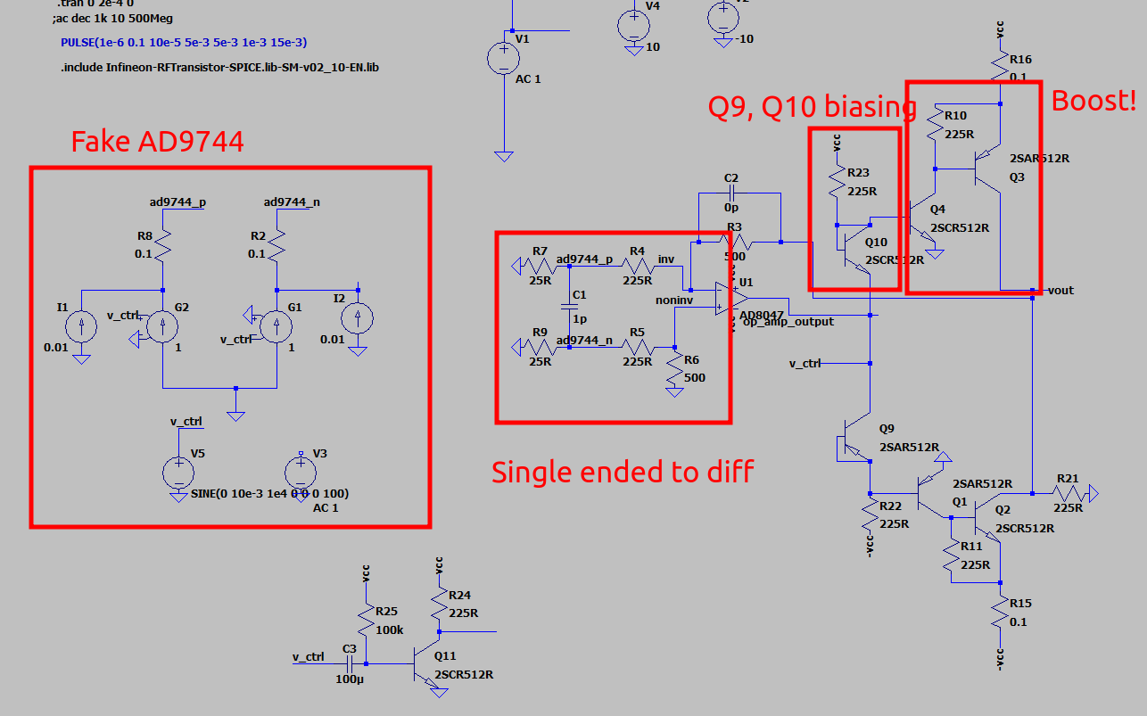
My waveform generator DAC is a AD9744. This is a differential output current DAC. The datasheet recommends this configuration of op-amp to convert this to a single ended signal:
However, this is not sufficient. I have always been frustrated at waveform generators that are 50R output impedance. What’s the deal with that? Where’s my big beefy 1A+ output stage? I would like one of those, and so this waveform generator shall have it. Also, 0→3.3V output? That’s obviously not going to work, we’re going to need +/- 10V swing at a minimum.
So basically what it looks like we will need is a power output stage. The art of electronics recommends this in order to increase the current capacity of an op-amp:
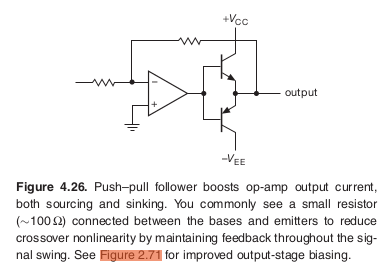
But in order to bias it properly to help avoid crossover distortion, you’ll need to add another transistor as a diode. Then, this only works as a buffer. So a +/-3.3V signal could not be converted to a +/-10V signal, as the “Booster” stage has no gain in and of itself.
That’s OK, transistors have gain. So we can just add another transistor to do that:
This is starting to look very unwieldy though. The signal has to go through a total of 3 transistors before it gets to the output!
So instead, let’s back-track a bit. We can make things simpler by moving to an op amp that can support the full output range of voltages. That way the boost stage does not have to have any gain to it, which as we shall see shortly makes things a lot easier.
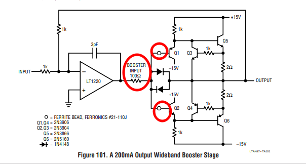
AN47 by Jim Williams
I was pointed to AN47 by Jim Williams which discusses precisely this topic on page 47 and appendix C. It is well worth reading, so I shall assume you have just gone and done so.
The overall goal here is to get something that is fast enough and of course does not oscillate. Per AN47 this is caused by:
- The op amp having a higher bandwidth than the booster stage
- The booster stage common collector amplifiers being driven with a low input impedance So to fix point 2 in particular, Jim adds a series resistor and two ferrite beads to avoid oscillations in the boost stage:
However there is a problem with this. Those resistors directly determine the bandwidth of the booster stage!
Here’s an example:
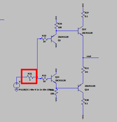
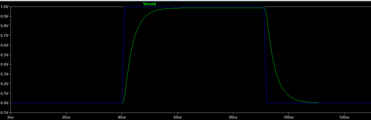
R32 changed to 100R:
Changing that to 1R:
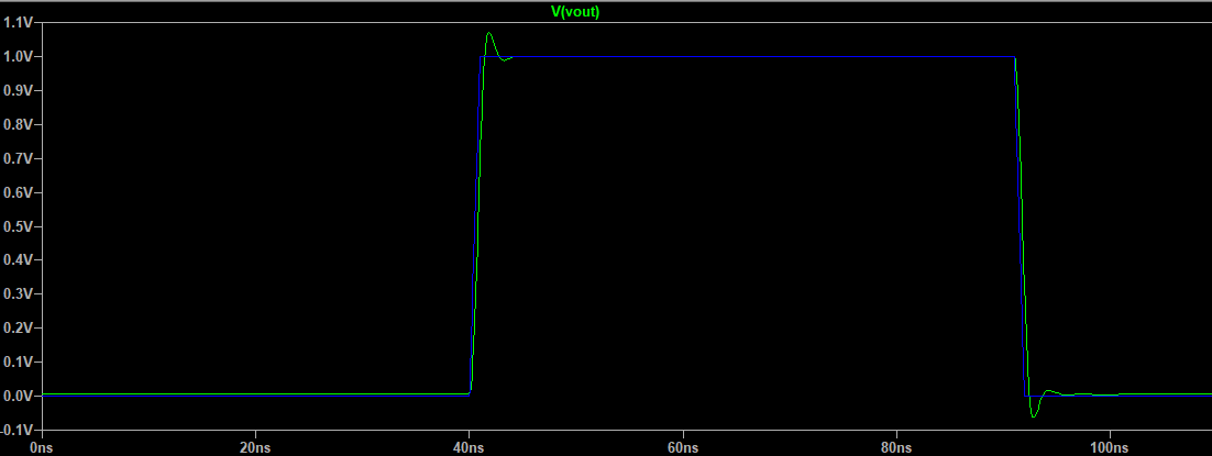
Huge difference!
And according to Jim, you would want to set it to 100R so as to avoid oscillations in Q1 and Q12. I went and looked up the sources as to why it is the case that emitter followers are prone to oscillation when driven with a very low source impedance but did not really grok the answers.
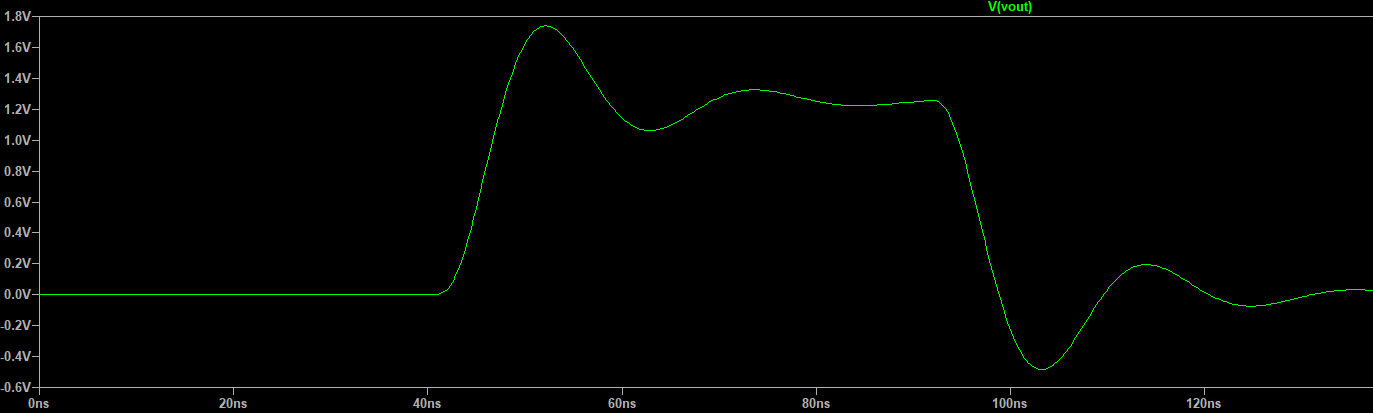
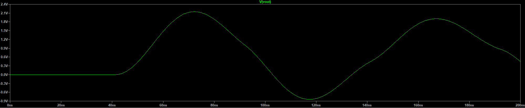
Now hooking up the above booster stage in a feedback loop with the op amp:
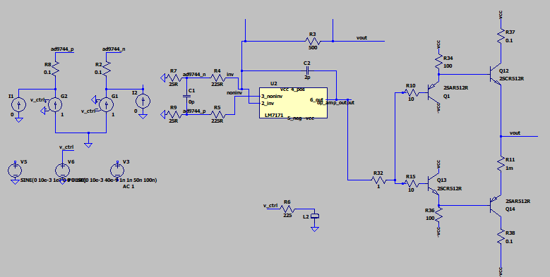
R32 = 1R:
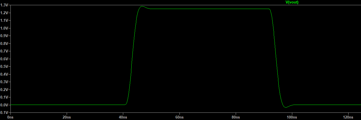
R32 = 100R:
R32 = 1kR:
So you can see that as predicted, decreasing the bandwidth of the booster stage as compared to the op amp stage is leading to instability. But according to the app note you would also expect that for the R32=1R case there would be some oscillation coming from Q1 and Q12 somehow.