In the previous episode of trying to get a fluxgate manetometer to work as a detector for a metal detector I decided that a possible reason that I didn’t observe much of a change in signal amplitude vs frequency was that the magnetometer was not sensitive enough. It was so insensitive that I had to wedge the copper/iron right up into the setup to measure anything:
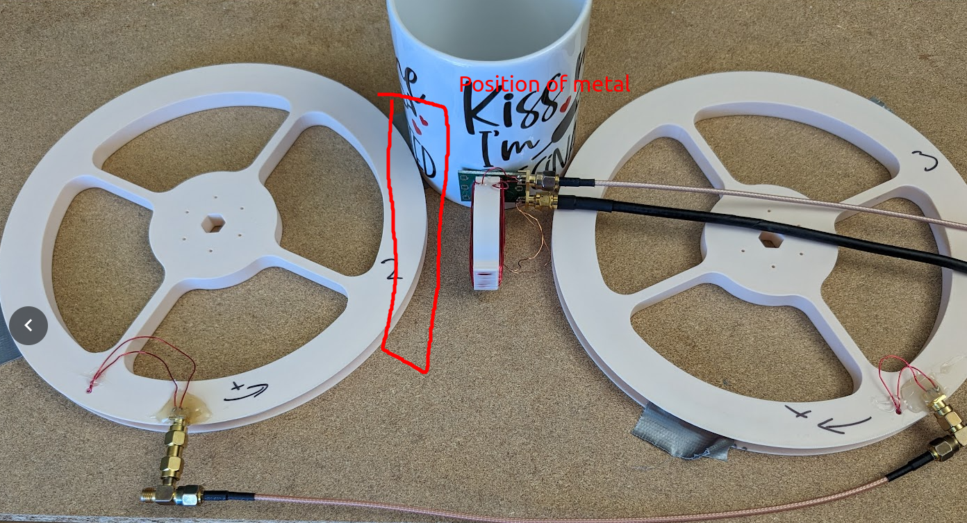
If the metal was in a more representative position I think the result might have been different.
Sampling to make it more sensitive
I already tried this but my DIY analog switch had too much charge injection to be useful, so I gave up. So as a backup plan I plopped down an analog switch PCB:
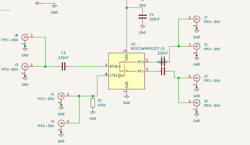
In the hopes that a dedicated IC would be much better. The actual part I used is the SN74LVC1G3157.
Results
Well, it isn’t any better really:
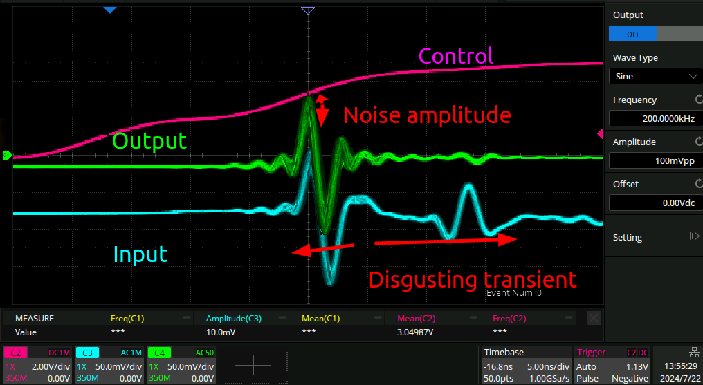
not only is there a huge amount of charge injection still, but there is actually quite a lot of noise turning up during the transient period, which is even worse.
Wrong circuit
I think I ordered the wrong part basically. What I should have done is used a sample and hold circuit rather than a analog switch.
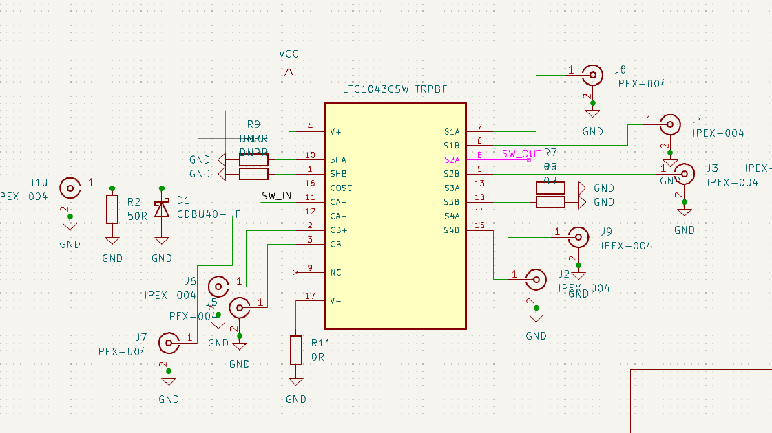
New circuit
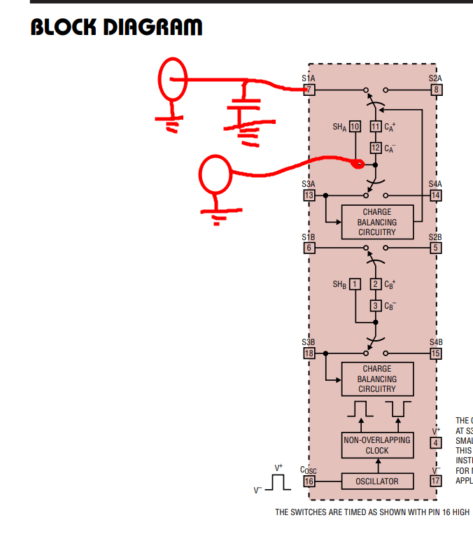
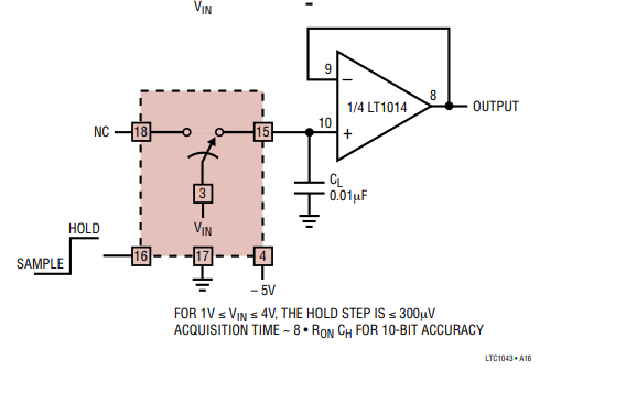
I poked about and learned of the existence of the LTC1043. It contains a whole bunch of components and differential whatnots, but it is possible to use one corner of it to make a sample and hold circuit:
Based on the immediate and totally predictable failure of the previous design I decided to put this new one in LT spice. Since this is a LT component this is actually possible:
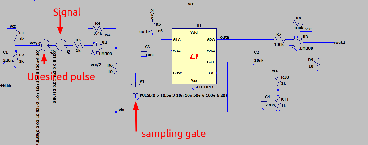
Here I have set things up so there is a sin wave signal corrupted with some spikes that we want to ignore:
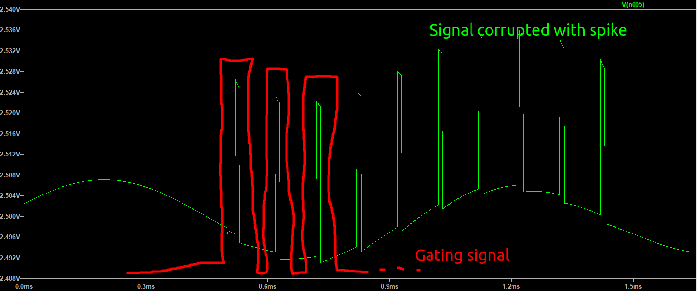
And here is the output from the op amp (before R6) as well as the output from the switch S2A:
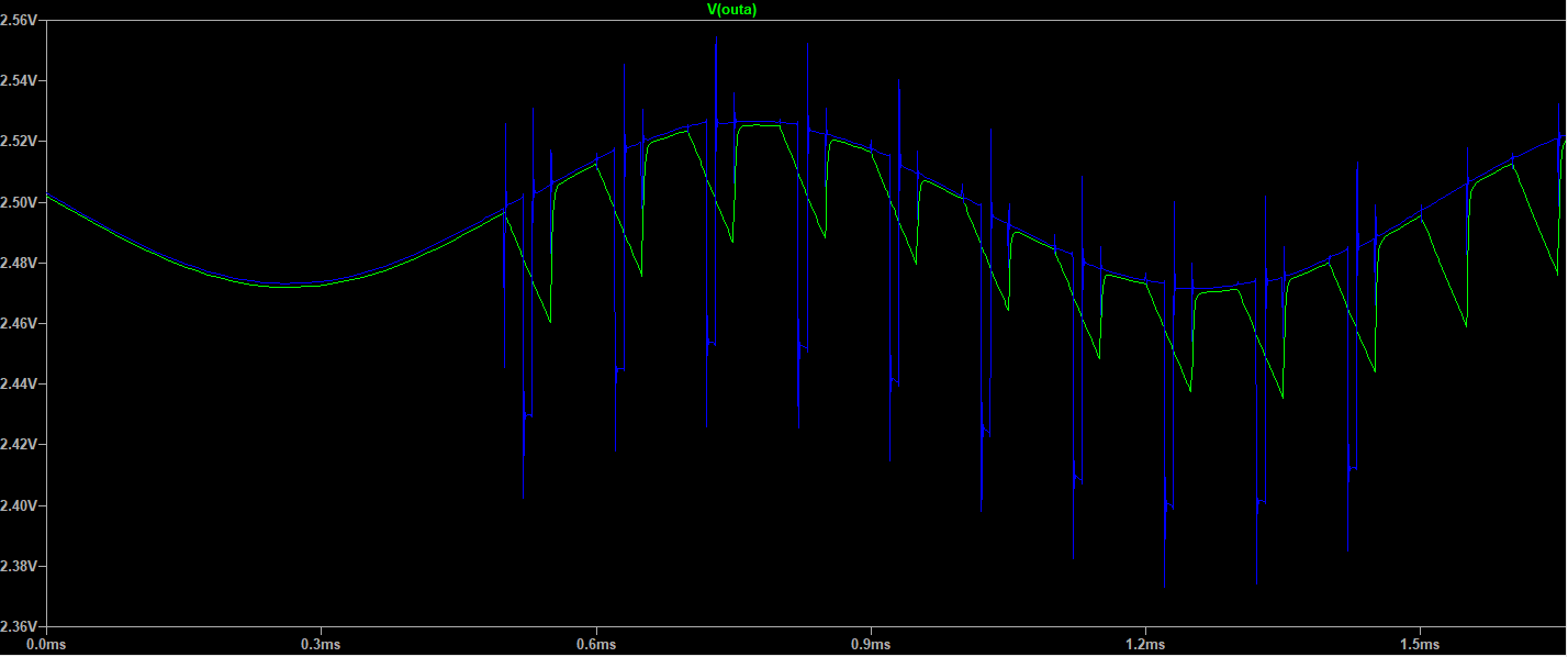
you can see that the output tracks the input quite well, but that the voltage sags down quite quickly outside the period where the switch is connecting the input and the output. I think that this is because the input impedance of the second op amp U3 is too high, i.e. 100kR is not enough. The idea here was that it would be a high impedance follower, but I think this might not be the proper design of op amp for that.
You can also see some spikes and whatnot going on on the input during the transition times. I think that’s the output capacitor C2 suddenly being connected to the load of U2. Increasing the value of R6 should help fix that, although of course it forms a lowpass filter so you can’t do it too much.
Real world, real results.
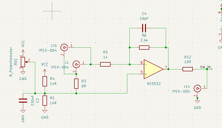
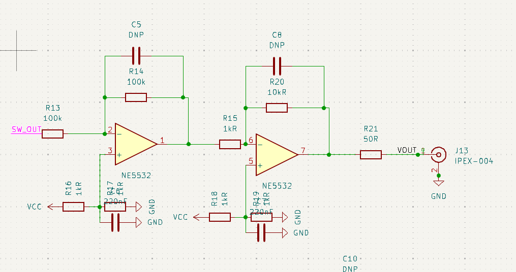
Schematic
Pretty straight forward amplifier going into a switch with an incorrectly configured buffer, followed by some more gain.
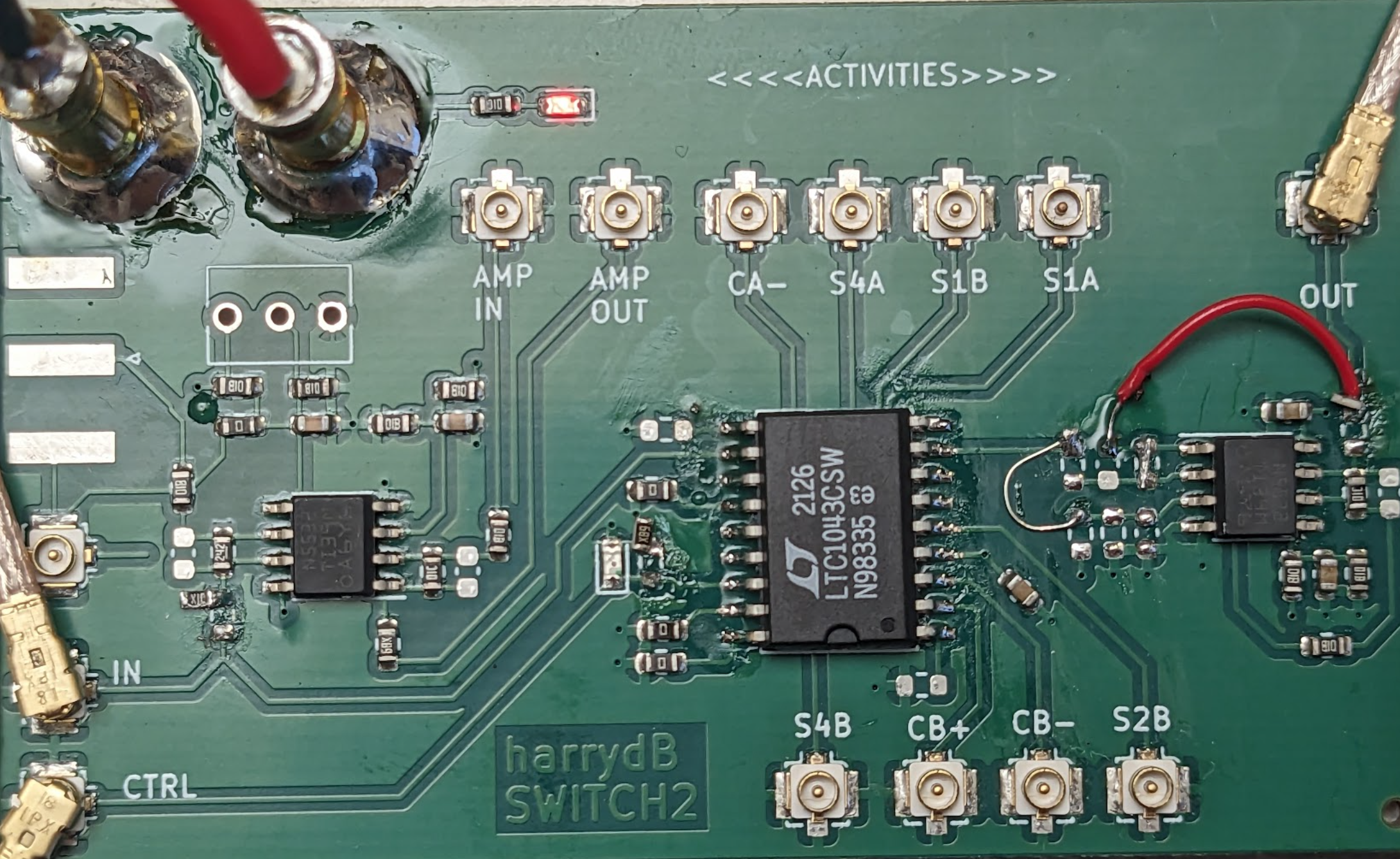
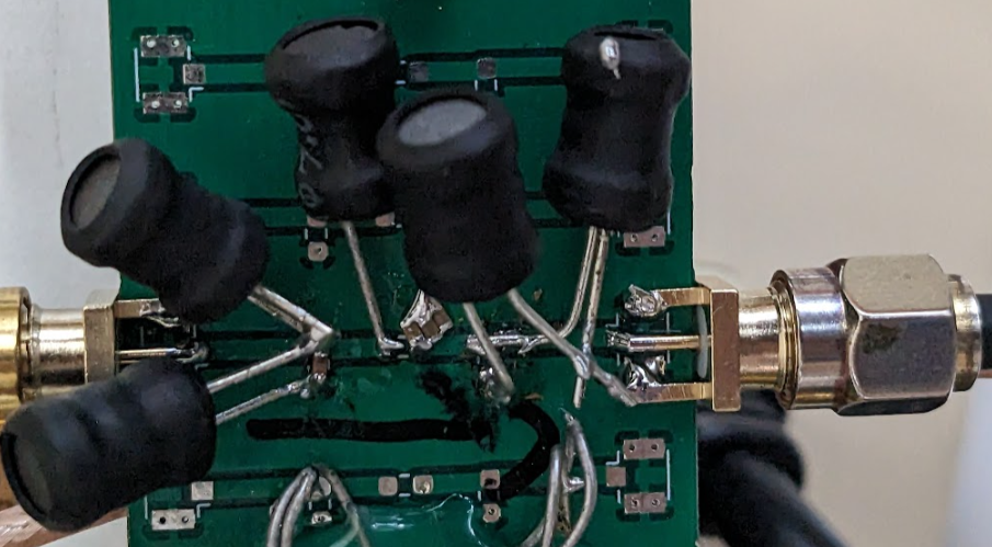
PCB:
Here is the PCB:
First results:
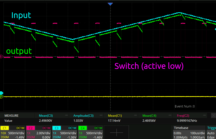
Looks pretty legit to me officer.
Charge injection
The main reason that I used this chip is that it alleges there is no charge injection when the input is around half the supply voltage:
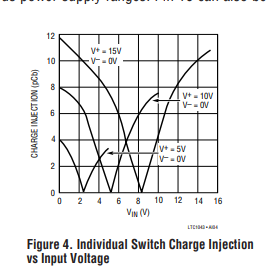
which means that for signals with 0 amplitude you should be all G.
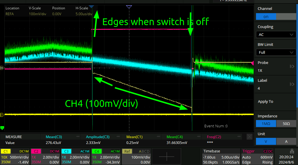
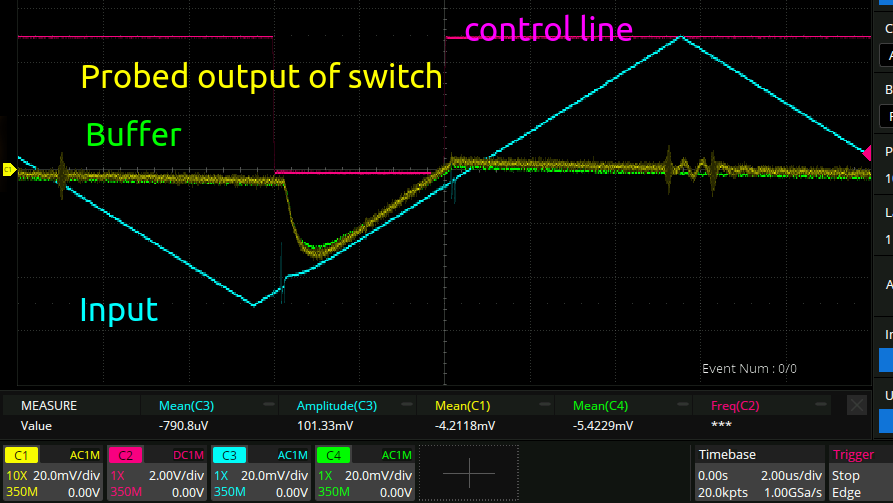
…this is interesting. Here I have zoomed in on one section. You can see that when the signal is switched there is indeed no charge injection. But when the signal is switched away, the signal starts to decay since there isn’t anything attached to that node of the circuit anymore. That’s obviously something that needs to be fixed. It should either hold its previous value (best) or decay to vcc/2 instead of GND. I wonder if it’s the lack of capacitance on the output combined with the input bias current of the op amp I am using…
RTFM
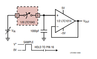
Here is the schematic for sample and hold from the datasheet:
…yeah. time to put 1nF on the output of my switch.
Nice! Now the droop has gone from like 200mV to 2mV. That’s pretty good. But if my signal is in the nV/uV range, that is still not close to good enough!
Rise time.
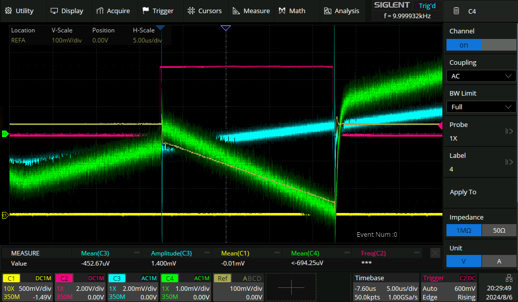
Here is the rise time with the 1nF cap attached:
Recall from before that the total width of our pulse was around 2uS. You can see from above already that the rise time of the signal is about, or just under, 2uS. So that’s not good, it would be nice if it was 2-10x faster.
Here is what the datasheet has to say on the topic:
So we need Ron:
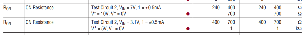
240*1e-9 = 240ns. But our rise time is like 10x 240ns! I don’t know why this is. In the above scope trace you can see a blip in the blue input as the control line is switched. That’s the impact of the scope impedance, which is clearly not a significant factor. I think maybe I need an op amp with a much lower input bias current.
While those are coming in the mail, I figured I would proceed regardless. The circuit should still work, it will just be less effective.
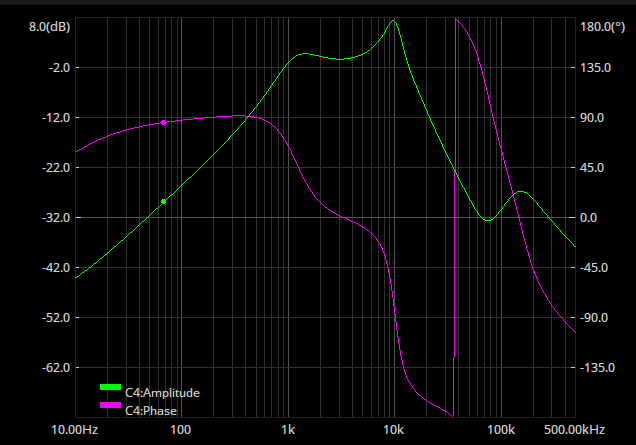
Bandpass filter
With all of the above working the circuit is definitely much more sensitive, it saturates with a small fraction of the earths magnetic field so I have been “nulling” the sensor by placing a magnet at the right distance and orientation so it measures 0 field in total. Then the signal that I get is dominated by mains hum at the low end and the 200+kHz pulses at the high end. Time for a filter:
My inductor kit just arrived in the mail so this is a good test. This is what the above kit looks like when constructed out of rando components:
 …not great. I suspect that the fact that my 15mH inductors have themselve 50R of DC resistance is not helping matters. It seems to be failing most at the high end though. I feel like that would be mostly due to self resonance of L2 being too low.
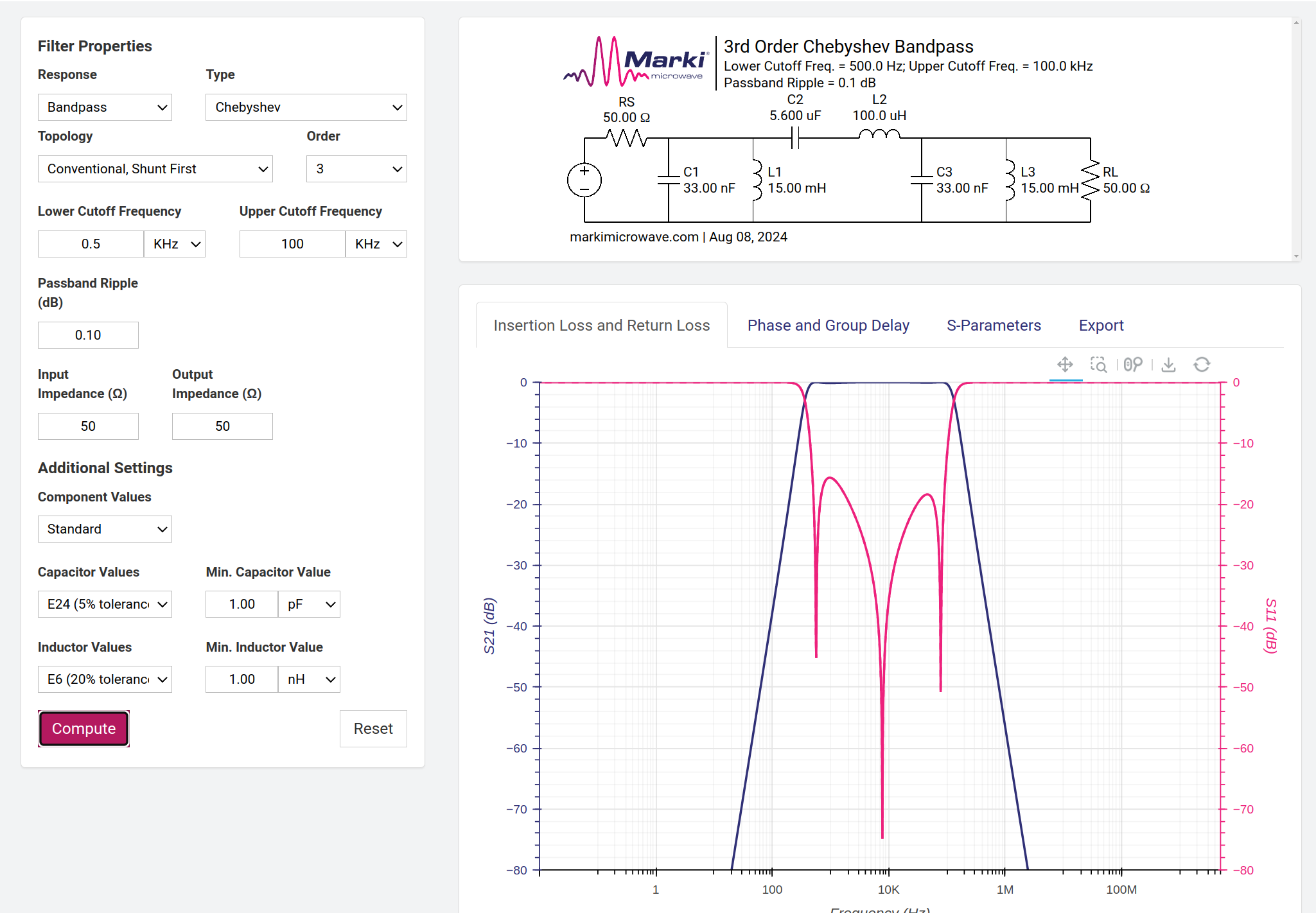
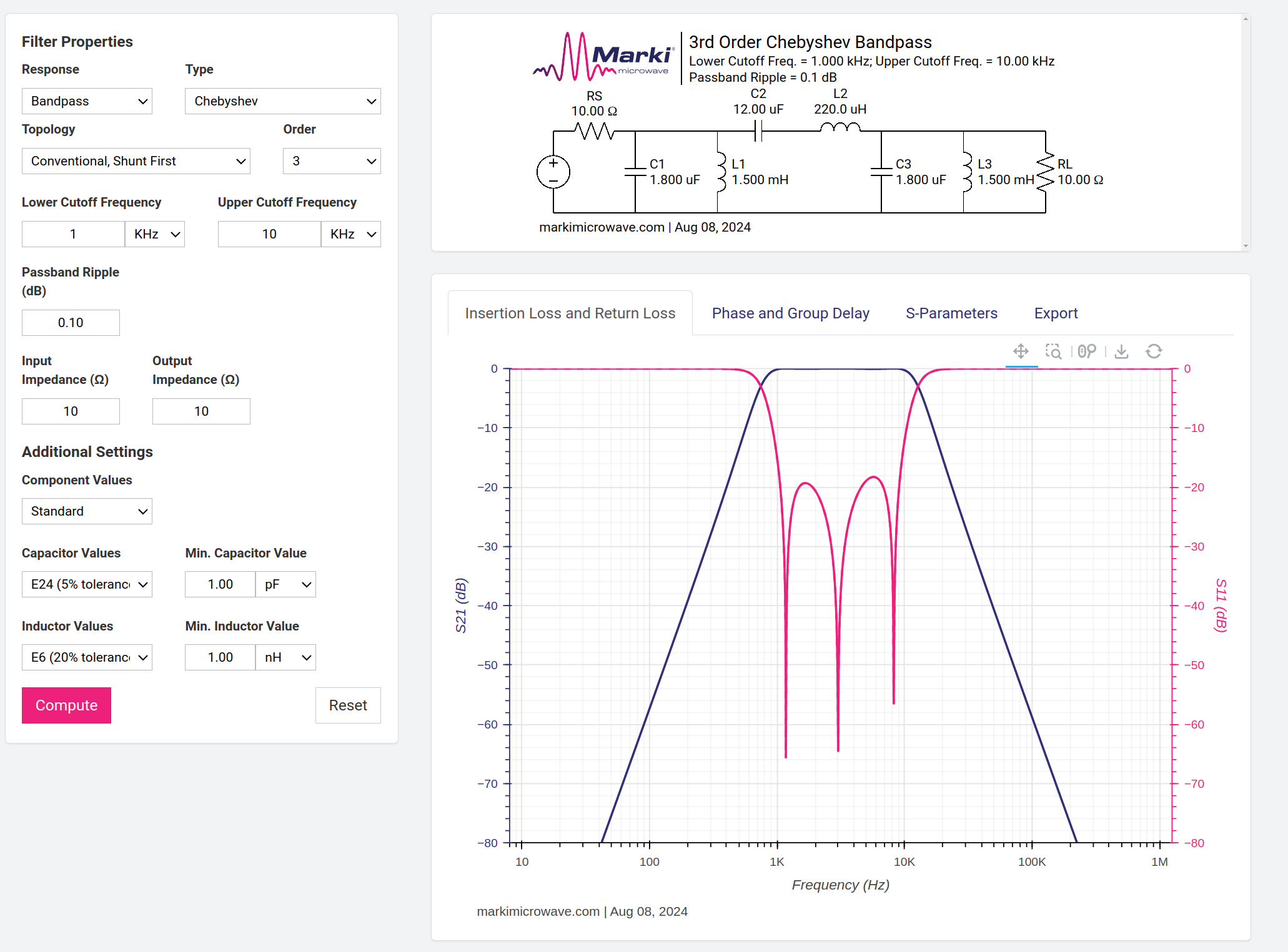
Changing the filter to 1kHz→10kHz would give more time for an imperfect rolloff to attenuate the ~1MHz pulses from the magnetometer, but that would also involve changing the top inductor to 220uH:
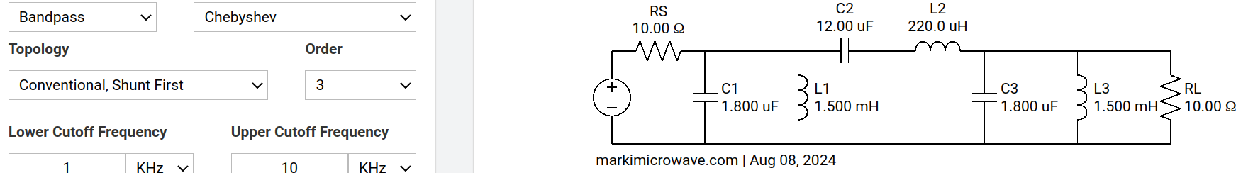
which would lower the SRF and make the performance of the filter worse at the high end. So I am hesitant to spend some time building one. The inductor sheet does not seem to come with a datasheet (hah) but when I filter digikey inductors from ones with the same inductance and similar DCR they all have SRF’s in the MHz range. So maybe I’m fine.
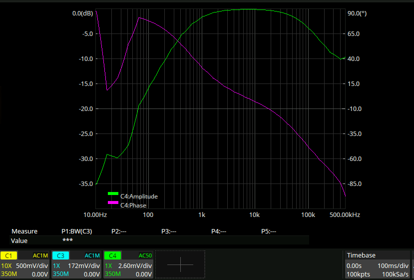
1-10kHz filter
That looks much better!
Filter sensitivity sniff test
Green here is the filtered result, blue is the unfiltered:
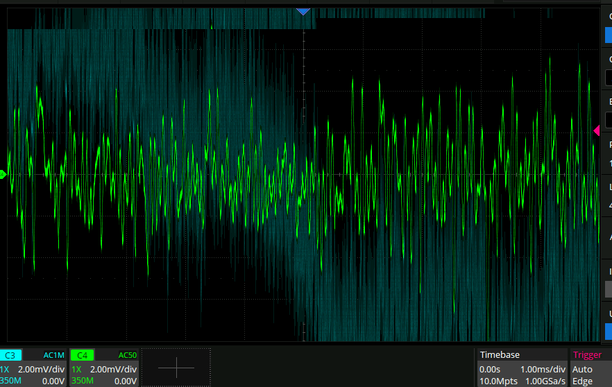
This looks pretty good. Now that the new op amp has arrived, it’s time to go back and put that in I think.
New op amp
I switched out the op amp that is the buffer on the output of the analog switch for the new OPA2392, with 10fA(!) of input bias current. This should allow me to use a significantly lower storage capacitor on the output of the switch, since it won’t be drained by the capacitor. I changed the cap from 1nF to 270pF and got this:
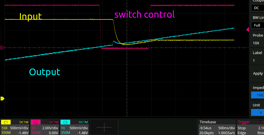
In the previous section the rise time was 1us, which was not comfortably within the sampling window. Here it is like 200ns, so you can see the output begin to track the input even within the sampling window. Noice!
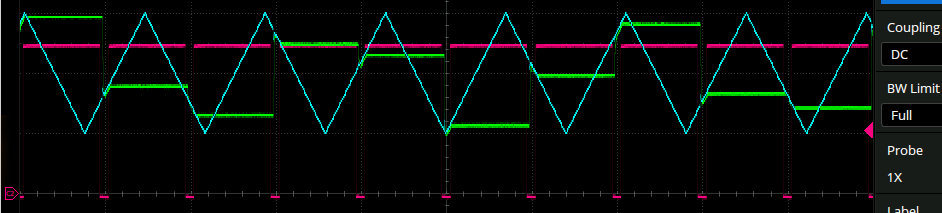
Here is another view zoomed out showing the wonderful sample and hold behavior on a test sawtooth waveform:
Some notes from debugging
Putting the above filter on the output of the OPA2392 results in some absolutely disgusting waveforms. This isn’t a surprise, since it is not specced at all to drive a 50R load. This led to a little confusion since the NE5532 also isn’t specced for this, but does not seem to have any pathological behavior if you do. Fortunately, I had a spare op amp output on my board already, so hooking that up as a buffer allowed me to pipe the output into the filter as intended:
One other thing: I noticed that the output was only nonsaturated for a very narrow range of magnetic fields. I took this to be because of the super high gain, and indeed this is the case, but the situation can be made much much better by AC coupling after the buffer:
since then the DC earth magnetic field does not contribute to the saturation, only the AC component from my drive coil.
Her is the output after making the above changes before and after the filter:
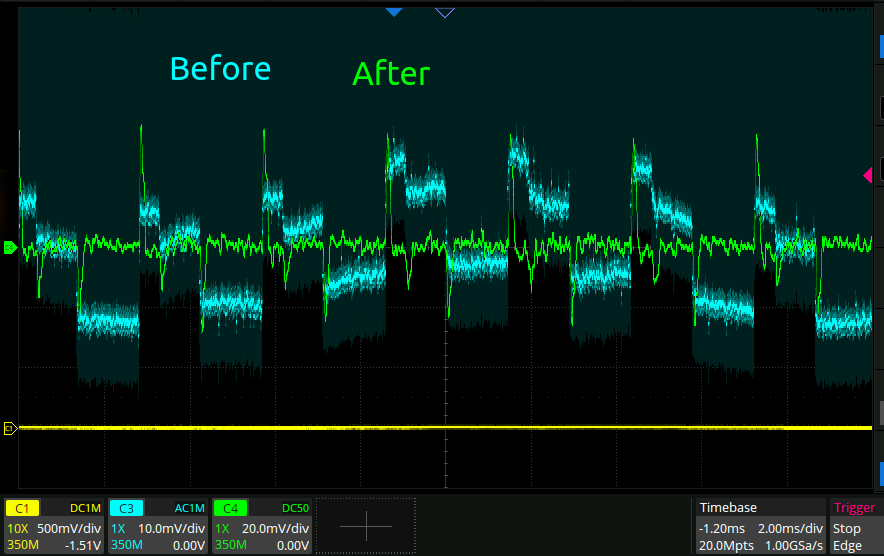
grrr. Previously the mains interference was sinusoidal, like all honest mains interference is. But here there is a square wave mains interference, so after filtering the edges still come through loud and clear. How annoying.
Sensitivity comparison
Throughout all of this there has been some kind of assumption that the sensitivity of the magnetometer was somewhere near that of a coil I have been using a coil to compare, and indeed the magnitude of the signal is comparable. But, I have not been using a coil with an appropriate capacitor to make the coil into an LC resonator. The comparison here is easy since I can directly swap out the magnetometer pickup coil for a coil of the same type as what I have been using as a drive coil.
Here we shall compare a 454uH pickup coil tuned to 8.5kHz with two 470nF caps in parallel. with the drive and pickup coils separated by about 1m, the coil has 200mVpp of signal, and when I zoom in a bunch it has about 2mVpp of noise. Here is an FFT of the noise:
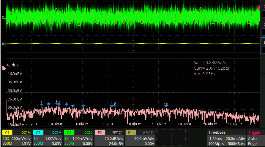
When I connect the magnetometer across the input again (after desoldering the caps) the signal has a magnitude of 20mVpp, and the noise has a magnitude of 4mVpp (after taking out the spikes coming in from the mains noise). Here is a spectrum coming from the magnetometer:
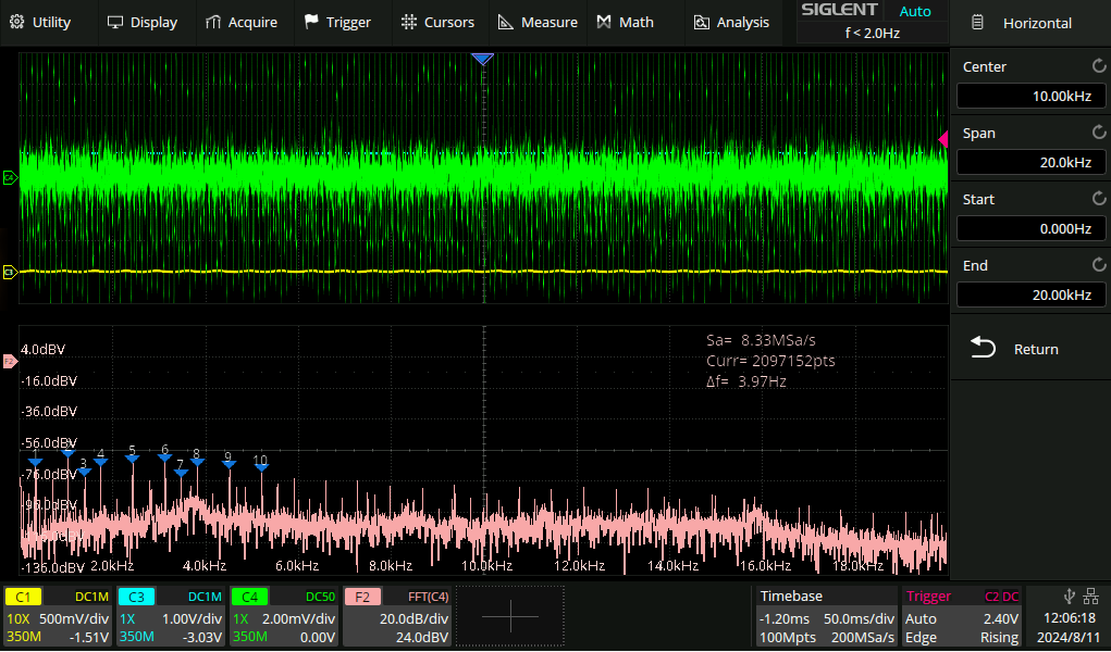
lots of disgusting spikes there. Regardless it looks like the main difference here is the sensitivity rather than the noise. I think I can chalk up the lower noise of the pickup coil to the lower bandwidth of the LC resonator. The reduced signal though is another matter. I suspect that the cause of this is that the “loop area” of the magnetometer is quite a bit lower than the coil, since the coil has a diameter of around 200mm and the magnetometer is only around 40mm.
The question is though what defines the ‘loop area’. You might think that it is the loop area of the pickup coil, but I do not think that this is the case since the purpose of that coil is just to pick up when the main magnetometer material saturates. Perhaps then it is the total amount of flux concentration that the magnetic material in the magnetometer manages. This sounds like a job for a textbook though.
“Magnetic sensors and magnetometers” has this to say on the topic of noise:
So it looks like changing the size of the sensor is futile. But one thing could easily be changed: I have been using a 50R impedance waveform generator with a 20V signal to power the drive coil. It sounds like I should change that to something else.
Actually:
So maybe there is something to building a large sensor!.
More current spikes.
Another thing to do is drive the drive coil harder. I’m going to add a cap in series with the output of my H bridge in an identical topology to the 20240522 Plasma toroid 4 decoupling.
I have no idea what the inductance of the drive coil is and given that it depends on the amplitude of the signal due to the saturation of the coil I’m just going to start with 10uF and go from there.
10uF looks like this:
which is a period of around 400ns. This is what it looks like with 100nF:
…I have never seen a more square resonance in my life. Down to 100pF!
…too far. 2nF looks like this:
I think what’s going on here is that the Q is suuper low because of the energy losses in the switching. The reason that I am even trying this resonant mode is because a single half bridge is one sided, so it can’t saturate the coil in both directions. Just to sanity check, this is what it looks like when I drive the coil with no capacitor, just the half bridge switching node to ground:
Half the half bridge:
Instead of having the coil go to ground, how about this:
 Now it can sink and source current! Never mind about the 20 ohms to ground, this ain’t an efficiency competition. This actually works quite well. Even when switching the coil current the voltage at the midpoint stays flat with 20uF of decoupling. However the output still goes all unstable at higher than 70kHz, just like with all of the above capacitor resonant setups:
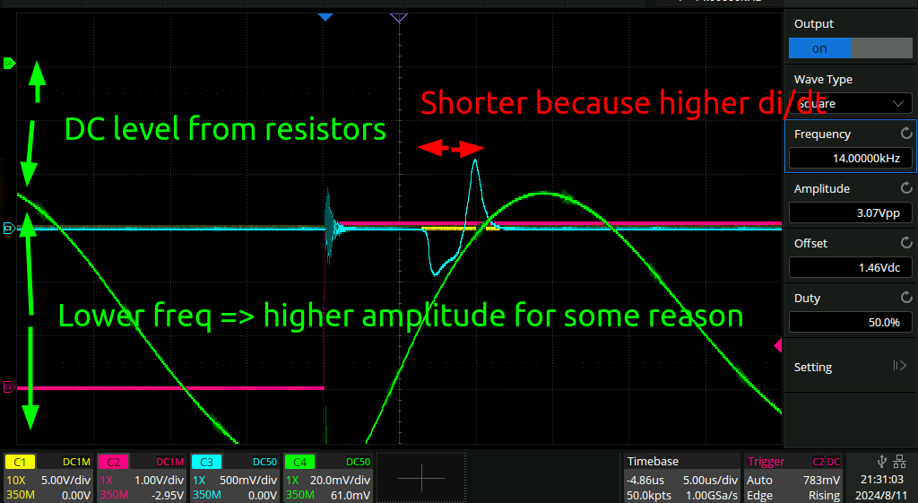
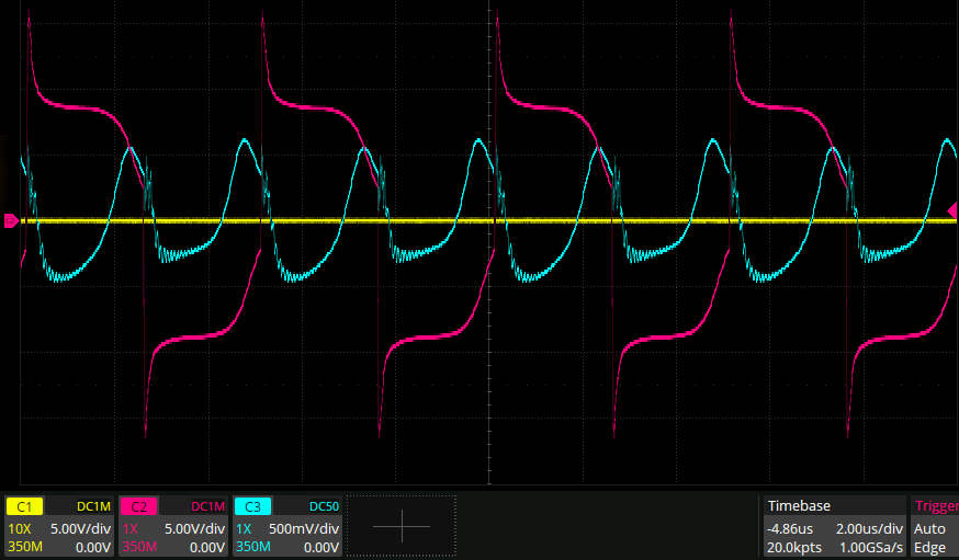
This is what the output looks like at a lower frequency of 14 kHz
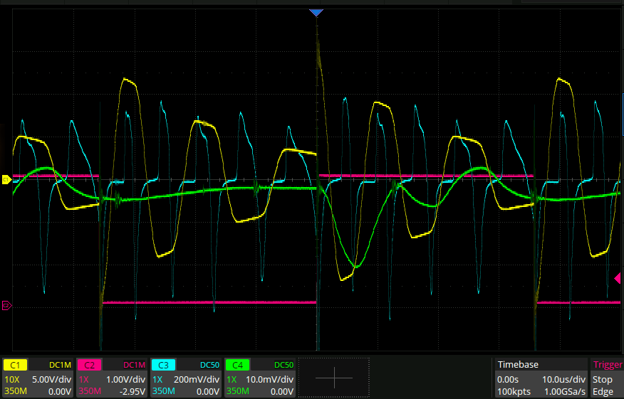
And here is the highest stable frequency:
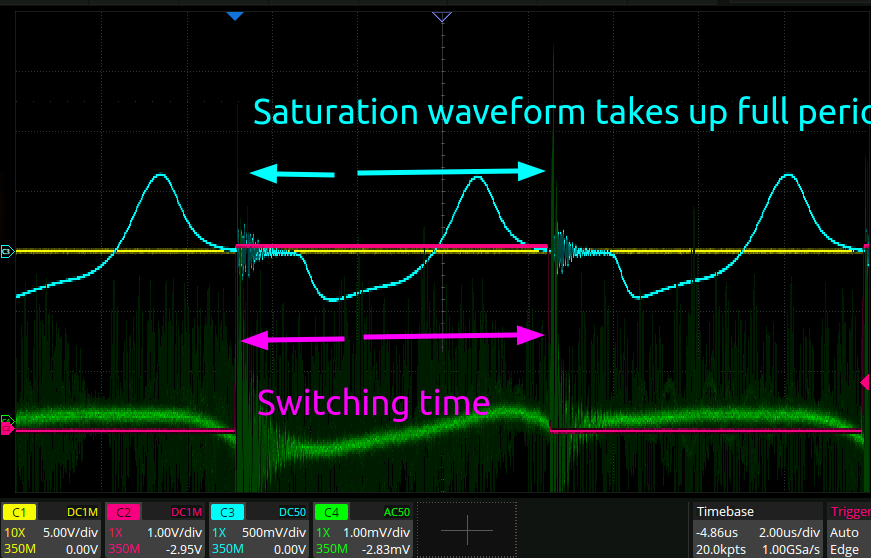
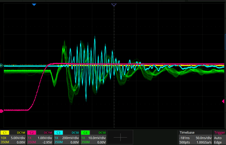
It seems pretty clear here that the reason the output goes all unstable at a higher frequency than this is because the hysteresis curve hasn’t gotten all the way back to the beginning, so “isn’t ready” for a new cycle to begin. From before we could see that the duration of the spike got shorter with higher di/dt, so you would think that just cranking up the supply voltage would do the trick here. It doesn’t though. Here is a picture that illustrates this shortening:
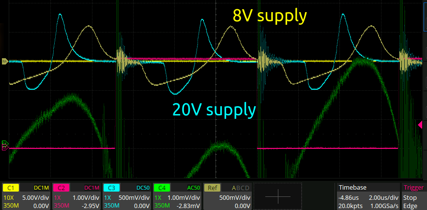
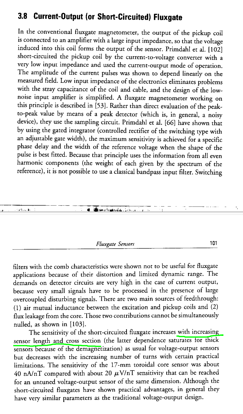
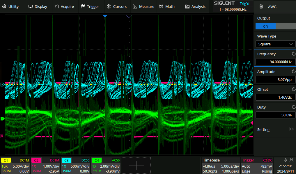
You can clearly see that at 20V supply there is loads of time between impulses. And yet, the maximum frequency that the circuit can be operated at stably is exactly the same - 73kHz. So how was I able to operate it at 200kHz with the waveform generator before? Time to plug that back in. Here is the AWG hooked up with a 20V amplitude square wave:
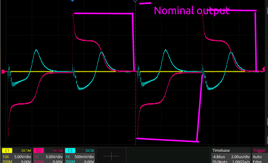
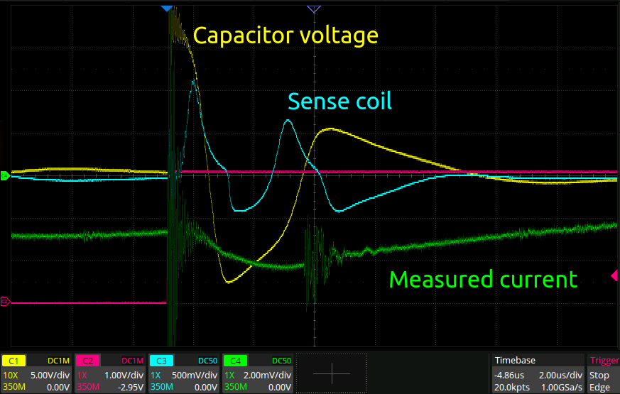
This is a 50R output so it shows clearly the magnetometer getting its core charged up, during which it has a high inductance and there is some imbalance in the coil, followed by the saturation of the core and the collapse of the voltage across the drive coil down to 0 as the resistance becomes equal to the few mOhm of DC coil resistance.
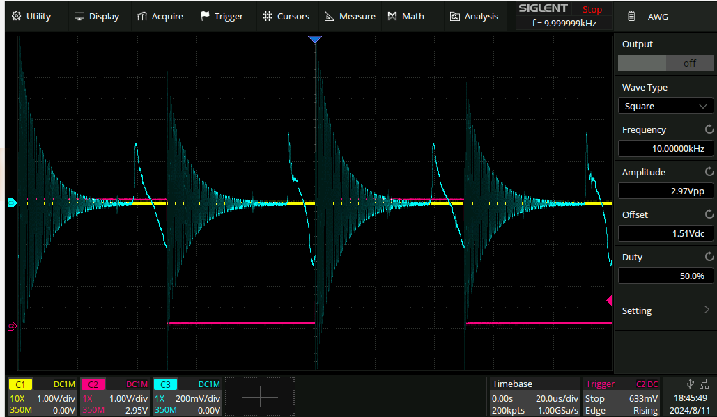
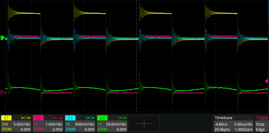
Here it is operating at 200kHz:
Perfectly stable. Why is that? I don’t really know. Thinking about the above paragraph though, maybe if I put some series resistance in with the coil like the waveform generator has I would prevent the instability. But at that point I would be just like the waveform generator! The whole idea here was that by driving it directly from the half bridge the core would saturate faster, and I would get a shorter higher amplitude peak that would be an overall better SNR. That doesn’t seem to have been the case though, so I think it’s safe to give up here. Probably a better core material is required.